Instructions for replacing the brake calipers on cars and light commercial vehicles
Please read and follow all instructions carefully. You’ll find the same instructions in the brake caliper pack. Remember to keep them for the entire product life cycle. Hand them over to the new owner if you sell your vehicle.
These fitting instructions are a guideline for standard repair work and do not take into consideration any special features which might apply to the different brake systems. The special instructions issued by vehicle and brake system manufacturers must be followed in detail.
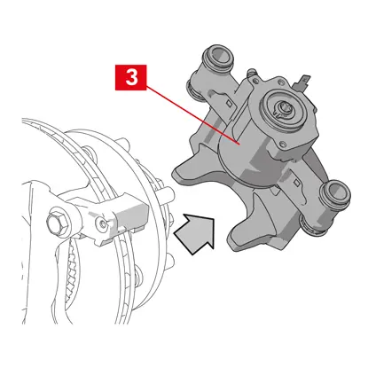
These fitting instructions are a guideline for standard repair work and do not take into consideration any special features which might apply to the different brake systems. The special instructions issued by vehicle and brake system manufacturers must be followed in detail.
This document provides instructions for the replacement of calipers:
1. Single-disc brake calipers
2. Dual-disc fixed calipers
3. Floating calipers with radial-mount pads, type 2x60/68.
2. Dual-disc fixed calipers
3. Floating calipers with radial-mount pads, type 2x60/68.
All the information on this instruction sheet applies to all three types of calipers, unless otherwise specified.
Replacement procedure
Before commencing replacement, ascertain that the spare parts used for replacement are suitable for the make and model of the vehicle.
- Remove the wheel.
- Make a note of the position of all the partially or fully disassembled components for correct reassembly.
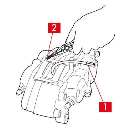
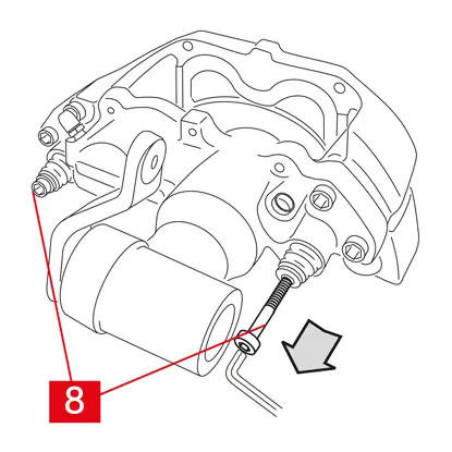
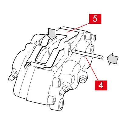
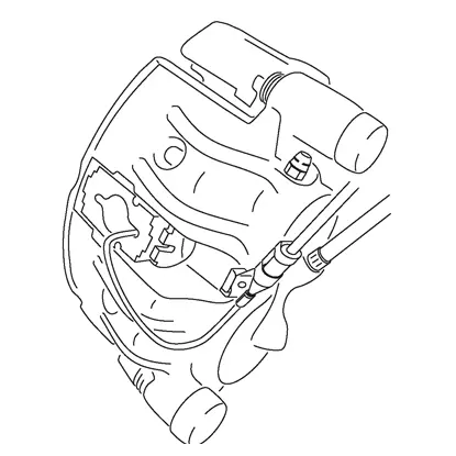
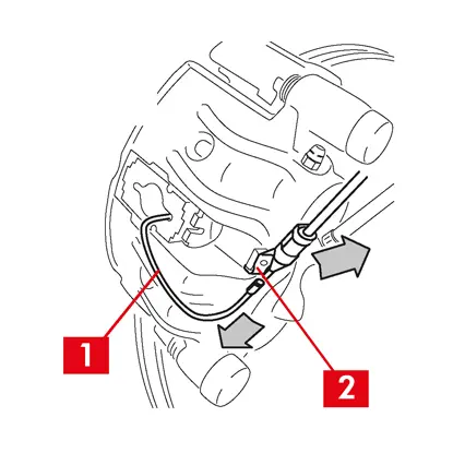
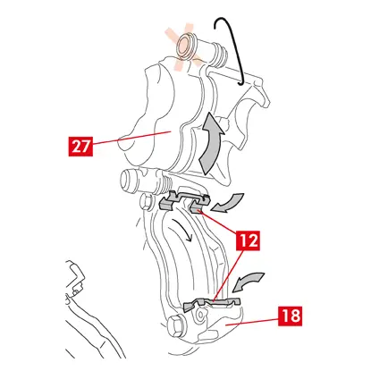
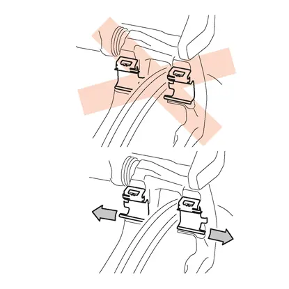
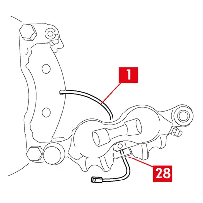
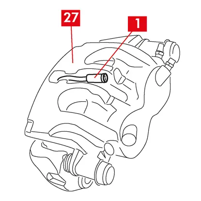
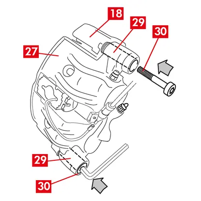
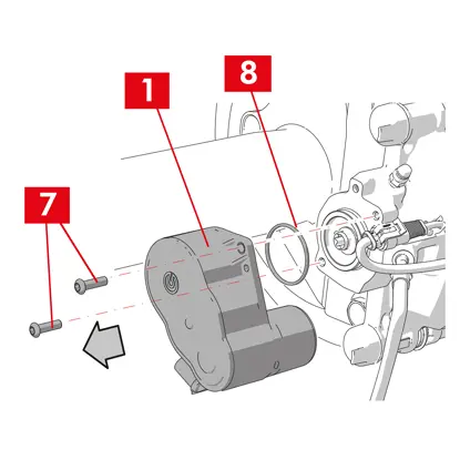
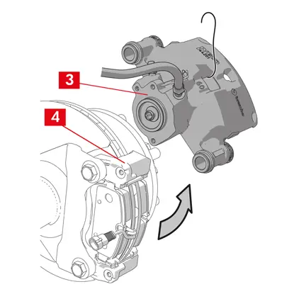
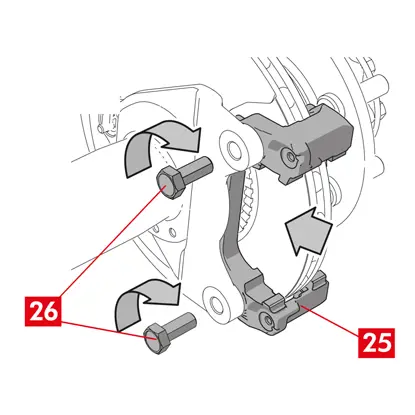
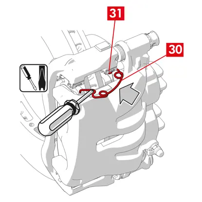
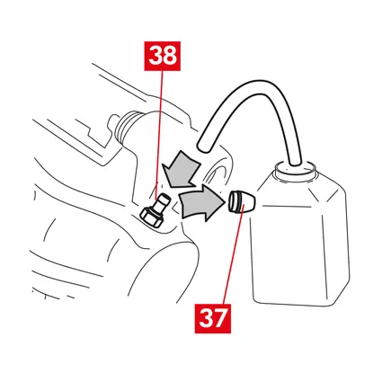
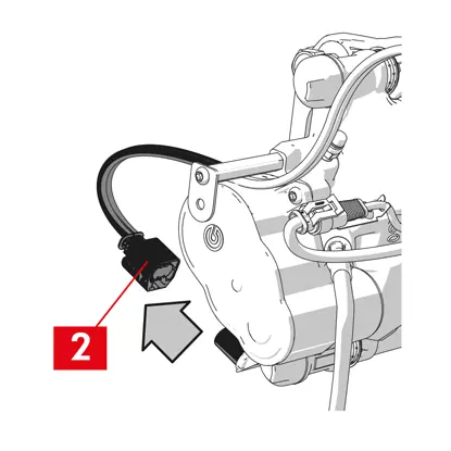
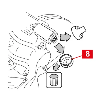
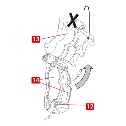
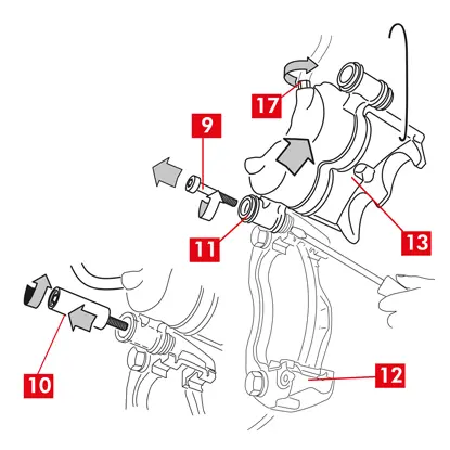
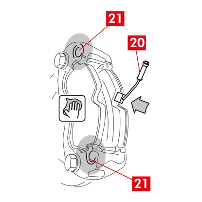
1. Disconnect the wear indicator cable (point 1), where present, from the terminal in the vehicle, releasing it from any attachments on the chassis and on the caliper.
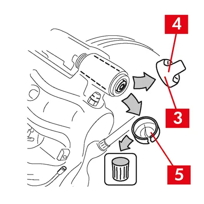
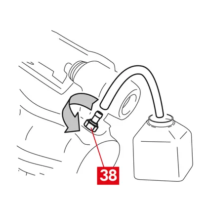
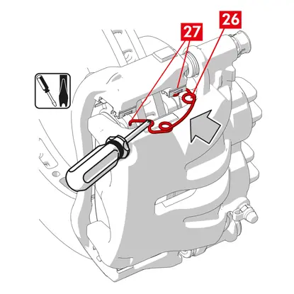
2. For models fitted with safety split pins (point 2), remove them using pliers.
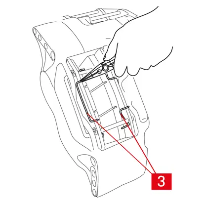
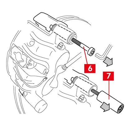
3. In the case of dual-disc calipers, remove the springs (point 3) using pliers.
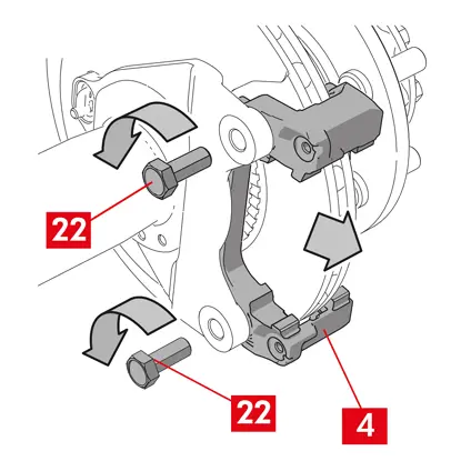
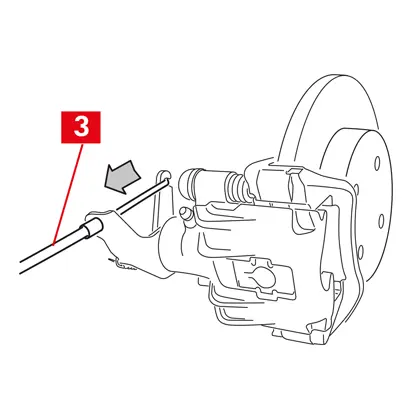
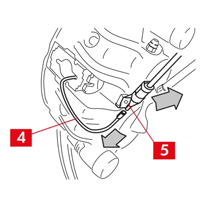
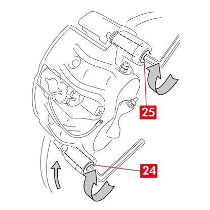
4. Pull out the pin(s) (point 4) using a hammer and pin driver. Pull out completely by hand, making sure you keep the springs (point 5) in position.
5. Remove the spring(s) (point 5). Check the fluid level. Open the brake fluid reservoir cap.
CAUTION! The piston pulling back steps described below cause the brake fluid level in the reservoir to rise. Make sure the level of brake fluid won’t cause a leak, as this would damage the painted parts of the vehicle.
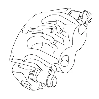
FIXED CALIPERS type A B
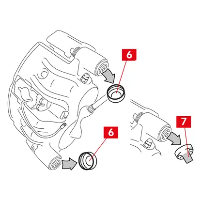
1. Pull away the pistons slightly using a retractor or other suitable tool, pressing on the pads (point 6).
The piston pulling back must subsequently allow the caliper to be loosened from the disc.
The piston pulling back must subsequently allow the caliper to be loosened from the disc.
2. If the design of the caliper allows it, remove the pads. Otherwise remove them after disassembling the caliper. If you intend to re-use the pads, mark the rotation direction of the disc on them with a marker.
FLOATING CALIPERS type C

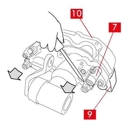
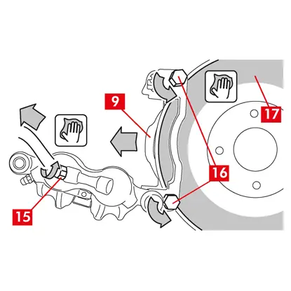
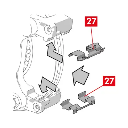
1. Take out the pads, while at the same time sliding the caliper body backwards and forwards on the guiding bushes (point 7). Sliding the caliper body pulls the pads slightly away from the disc, making them easier to remove.
If the dent created by the disc wear obstructs the extraction of the pads, disassemble the caliper body:
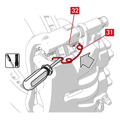
1. Disassemble the screws (point 8) using a spanner.
2. Using a screwdriver, prise the guiding bushes out from the dedicated seats.
3. Take out the guiding bushes (point 7) enough to detach them from the caliper bracket (point 9).
4. Separate the caliper body (point 10) completely from the caliper bracket (point 9) and hang it into the vehicle chassis using an S-shaped hook.
5. Take out the pads.
6. If you intend to re-use the pads, mark the rotation direction of the disc on them with a marker.
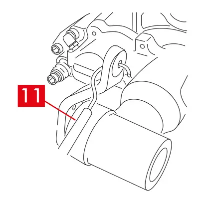
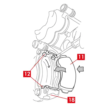
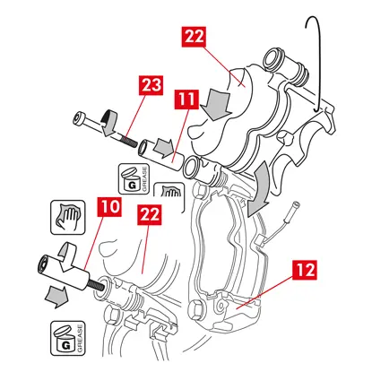
7. For the rear calipers (with parking mechanism), disconnect the parking control cable (point 11).
DANGER! The brake fluid lines must remain loose and not stretched. If you stretch the lines, they could break and brake fluid could leak out.
For all types of calipers
1. Close the brake fluid reservoir cap.
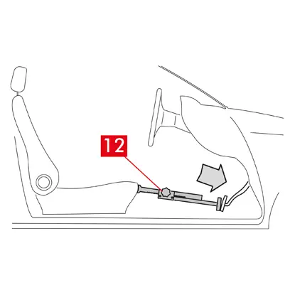
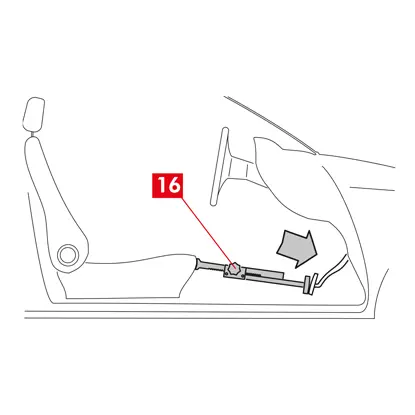
2. Place a spacer (point 12) inside the passenger compartment between the seat and the brake pedal to make sure the pedal remains pressed for the duration of these operations.
WARNING! This allows the brake hydraulic circuit to be closed, avoiding any brake fluid from leaking.
CAUTION! During all the phases described below, make sure the brake fluid does not come into contact with parts of the vehicle which would be damaged, especially painted parts. Promptly wipe off any accidental fluid splashes or leaks with kitchen towel and clean with water.
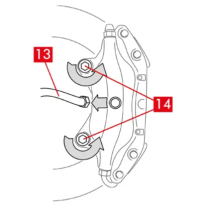
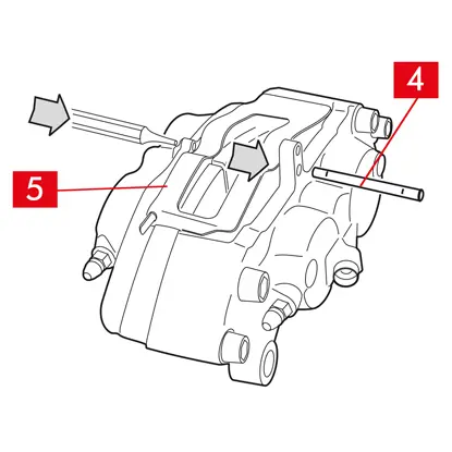
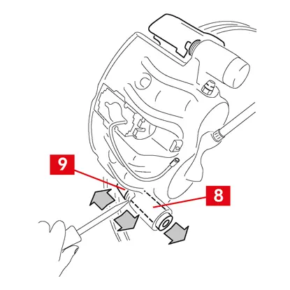
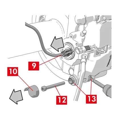
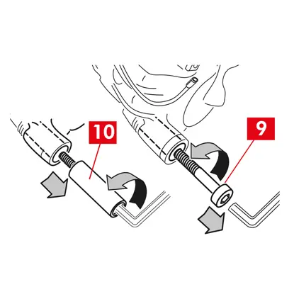
3. Loosen the supply line (point 13) on the caliper enough to be able to screw it off completely by hand, but avoid any brake fluid leaking out.
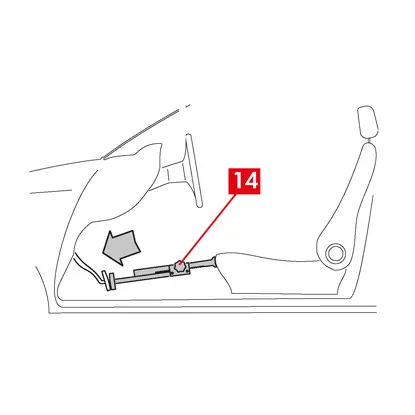
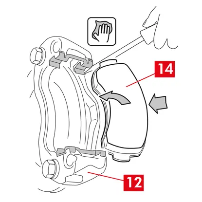
4. Unscrew the fastening screws (point 14) using an open-ended spanner and remove the caliper from the axle.
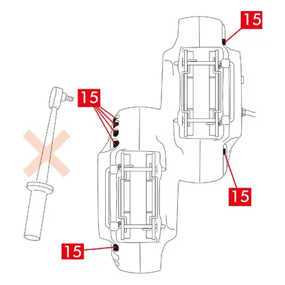
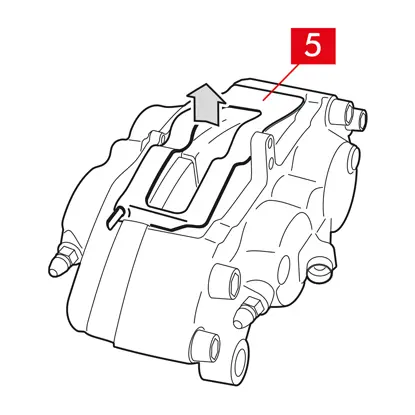
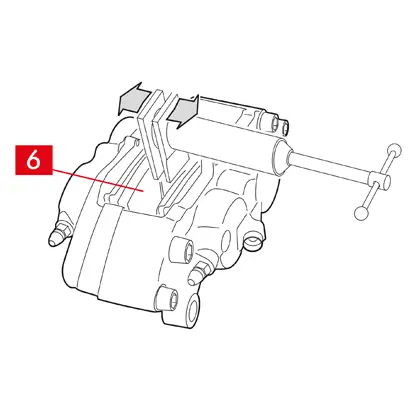
5. CAUTION! In the case of dual-disc calipers, disassemble only the axle fastening screws. Do not disassemble the screws (point 15) joining the half-calipers together.
6. Detach the supply line (point 13) completely from the caliper.
7. Promptly wipe off any brake fluid leaks.
8. Keep the supply line raised to prevent any accidental fluid leaks.
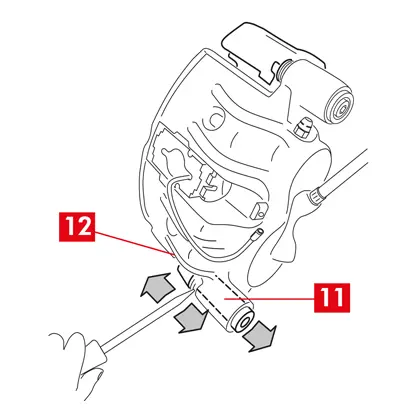
9. Pull away the caliper to be replaced.
9. Pull away the caliper to be replaced.
Fitting procedure
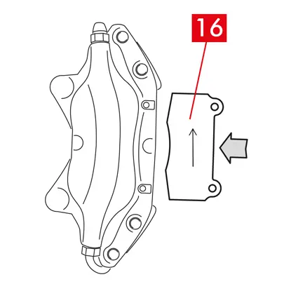
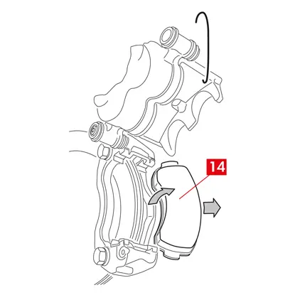
1. Insert the pads (point 16) in the new caliper.
WARNING! Any arrows stamped on the pads must be pointing in the disc rotation direction.
DANGER! Pads must be inserted with the friction material facing the disc.
2. WARNING! If the design of the caliper allows it, the pads can also be inserted after the caliper has been fitted, straight after the “tighten the fastening screws” step.
DANGER! Make sure the friction surfaces are not soiled with grease, otherwise all traces of grease will have to be removed with sandpaper.
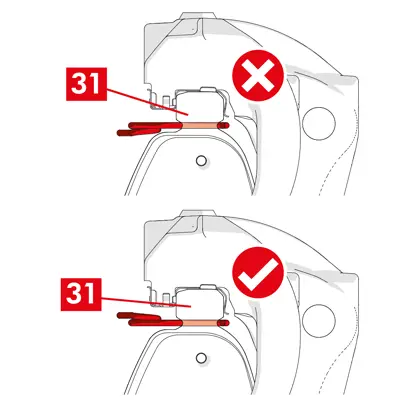
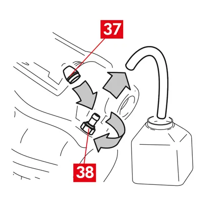
3. Reinsert the springs (point 5) and pins (point 4) in the dedicated seats in the caliper and pads. The pins must be driven all the way in using a hammer and pin driver.
Observe the direction of orientation when fitting the springs.
Observe the direction of orientation when fitting the springs.
4. Check the springs are correctly positioned.
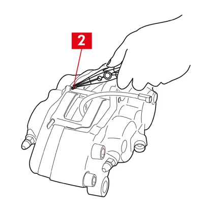
5. For models fitted with safety split pins (point 2), reposition them using a pair of pliers.
6. Check the split pins are correctly positioned.
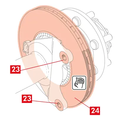
7. Clean the braking surface (point 17) on the disc (point 18) using a degreasing product (e.g. solvent SE 47).
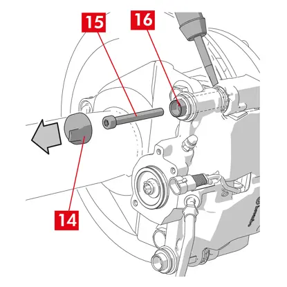
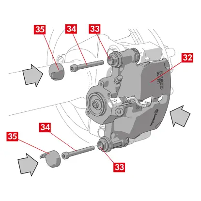
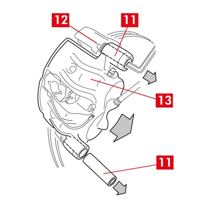
8. Position the new caliper on the axle, inserting the disc (point 18) between the pads.
9. Tighten the fastening screws (point 14) with an open-ended spanner, applying the tightening torque recommended by the vehicle manufacturer.
Alternatively, use the following recommended tightening torques for reference:
| Type of screw | M12x1,25 | M12x1,5 | M14x1,5 |
| Tightening torque | 115 Nm | 125 Nm | 180 Nm |
10. Reconnect the wear indicator cable, where present, to the terminal in the vehicle and to any attachments on the chassis and on the caliper.
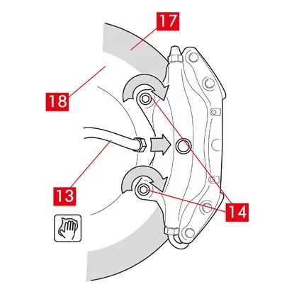
11. Reconnect the brake fluid supply line (point 13).
12. Remove the spacer you previously placed inside the passenger compartment, thereby releasing the pedal from the brake and allowing the circuit to reopen.
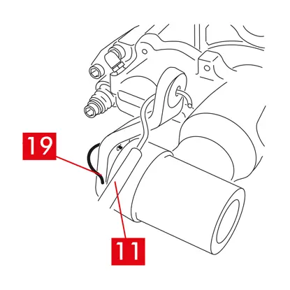
13. For the type C rear calipers (with parking mechanism), reconnect the parking control cable (point 11).
14. Remove the lever locking pin (point 19).
15. Apply the parking brake inside the vehicle. Repeat the process several times, until the stroke of the braking mechanism lever is re-established to minimum values.
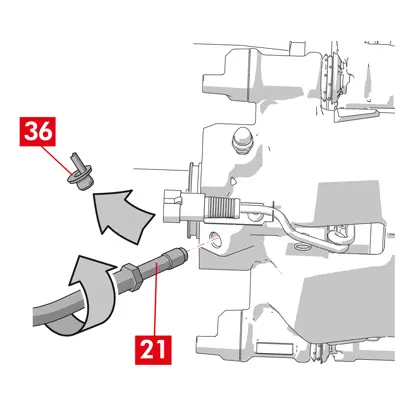
16. Open the brake fluid reservoir cap.
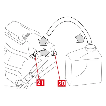
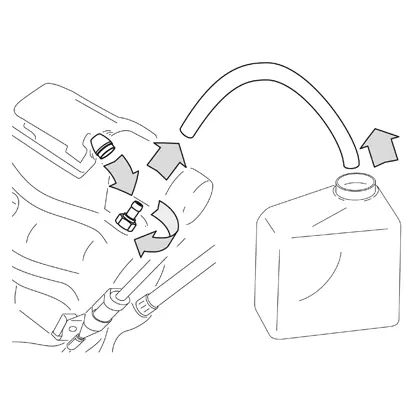
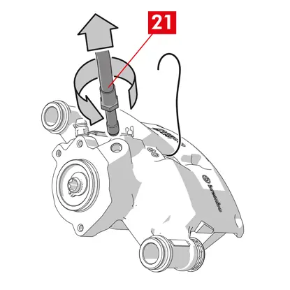
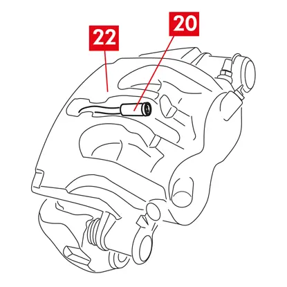
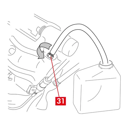
17. Remove the protective cap (point 20) and connect a transparent tube to the bleeder plug (point 21) on the caliper, the ends of which should be placed in a container to collect any fluid.
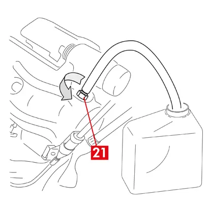
18. Open the bleeder plug (point 21).
19. Repeatedly press the vehicle brake pedal until brake fluid starts to flow out of the bleeder plug.
20. Holding down the pedal, close the bleeder plug. Release the pedal, wait a few seconds, then repeat the process until fluid without any air bubbles flows out and until the usual resistance and travel of the brake pedal are restored.
21. Tighten the bleeder plug applying the tightening torque specified in the table:
| Bleeder plug | M6x1 | M6x1 | M6x1 | M6x1 |
| Tightening torque | 5÷7 Nm | 7÷10 Nm | 17÷20 Nm | 18÷22 Nm |
22. Remove the transparent tube and reposition the protective cap on the bleeder plug.
23. Repeat the bleeding procedure for any other bleeder plugs.
24. After the bleeding process, pull back the pistons in the caliper completely using an appropriate tool (such as a retractor) and then top up the fluid level, as recommended by the manufacturer.
25. Close the brake fluid reservoir cap.
26. With the engine running, apply strong pressure to the vehicle brake pedal and check there are no fluid leaks from the caliper or abnormal pressure losses in the circuit and that the rear brake lights come on.
DANGER! If fluid is leaking from the caliper, repeat all the steps set out in this document to pinpoint the cause and remedy the problem.
27. In the case of calipers with an incorporated parking brake, connect the parking brake cable terminal to its seat on the caliper. Pull and release the cabin parking brake repeatedly.
28. Refit the wheel.
29. If the pads are new, run them in; follow the instructions provided with the spare pads.
Here the instructions for the replacement of brake calipers:
Floating calipers with central spring
Floating calipers with 2 or 4 side springs and residual torque reducing springs.
All the information on this instruction sheet applies to both types of calipers, unless otherwise specified.
Replacement procedure
Before commencing replacement, ascertain that the spare parts used for replacement are suitable for the make and model of the vehicle.
- Remove the wheel
- Make a note of the position of all the partially or fully disassembled components for correct reassembly.
1. Disconnect the wear indicator (point 1), where present, from the terminal in the vehicle, releasing it from the shim (point 2) that secures it to the caliper and from any attachments on the chassis.
2. Remove the protective caps (point 3) from the guiding bushes.
3. If the cap has a lip (point 4), snap off the cap by pulling on the lip (point 4) with your fingers.
4. If the cap is made of hard plastic (point 5), prise if off with a screwdriver. Removing the cap will break it.
WARNING! Do not reuse the disassembled hard plastic cap.
CAUTION! The guiding bush to disassemble must be the one that allows the caliper body to turn without causing the brake fluid supply line to stretch.
WARNING! There are two types of guiding bushes:
- with separate screw
- with incorporated screw
- with incorporated screw
5. Loosen and completely remove the screw (point 6) or incorporated guiding bush (point 7) using a spann
WARNING! If there are any brake pads glued to the caliper, detach them using a screwdriver.
DANGER! Opening the caliper body may cause the residual torque reducing springs to spring open.
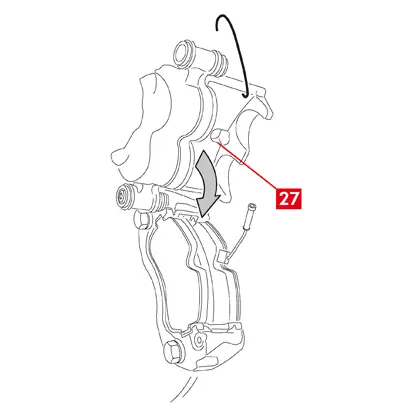
6. In the case of a non-incorporated guiding bush (point 8), pull the guiding bush out of the caliper bracket (point 9) prising it out of its seat with a screwdriver.
7. When replacing the caliper on rear wheels with suspension and leaf springs, both the guiding bushes (point 8) must be removed to separate the caliper body (point 10) completely from the caliper bracket (point 9).

8. Pull the caliper body (point 10) away from the caliper bracket (point 9) by twisting it around the other guiding bush until the pads come out of the caliper bracket. Attach the caliper body to the vehicle chassis using appropriate supports.
9. Remove the pads (point 11) and springs (point 12) without causing any damage so you can reassemble them onto the new caliper.
10. Use a marker to mark the direction of rotation of the disc on the pads to avoid reassembling them incorrectly.
11. If they are still in position, remove the residual torque reducing springs (point 13).
12. Place a spacer (point 14) inside the passenger compartment between the seat and the brake pedal to make sure the pedal remains pressed for the duration of these operations.
WARNING! This allows the brake hydraulic circuit to be closed, avoiding any brake fluid from leaking.
CAUTION! During all the phases described below, make sure the brake fluid does not come into contact with parts of the vehicle which would be damaged, especially painted parts. Promptly wipe off any accidental brake fluid splashes or leaks with kitchen towel and clean with water.
13. Loosen the supply line (point 15) on the caliper enough to be able to screw it off completely by hand, as this will avoid any brake fluid leaking out.
14. Unscrew the fixing bolts (point 16) using an open-ended spanner and remove the caliper bracket (point 9) from the hub bracket.
15. Detach the supply line (point 15) completely from the caliper body.
16. Promptly wipe off any brake fluid leaks.
17. Keep the supply line raised to prevent any fluid leaks.
18. In the case of calipers with an incorporated parking brake, disconnect the parking brake cable from its seat on the caliper.
19. Pull away the caliper to be replaced.
20. Clean the braking surfaces (point 17) on the disc using a degreasing product (e.g. Solvent SE47).
Caliper fitting procedure
CAUTION! Do not disassemble the protective cap from the fluid inlet hole on the new caliper until you connect the supply line to it.
Lubricate the bushes and dust covers using the grease provided before fitting the new caliper.
WARNING! EUH210 - Safety data sheet available upon request.
WARNING! EUH208 - Contains N-alkylated benzotriazole. May cause an allergic reaction.
1. Remove the protective caps from the bushes, where present.
2. Loosen the screws or guiding bushes with incorporated screw.
3. In the case of separate screws, take the screws out completely.
4. Pull the caliper body away from the caliper support.
WARNING! To avoid damaging the dust covers, pull out the bushes from the side of the cover.
5. Remove the covers.
6. Thoroughly clean all the components to be fitted, the bush seats and the cover seats using appropriate products (e.g. a damp cloth).
7. Clean the mounting faces on the hub bracket.
8. Position the new caliper bracket (point 18) by inserting it in the disc.
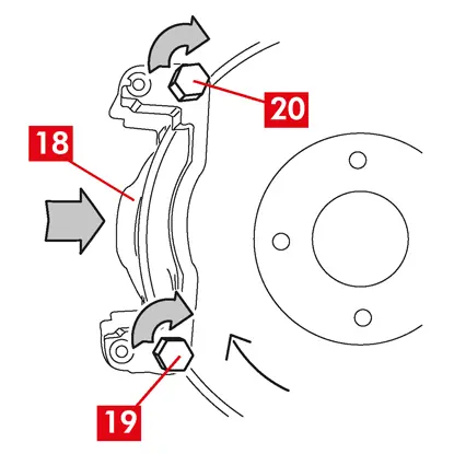
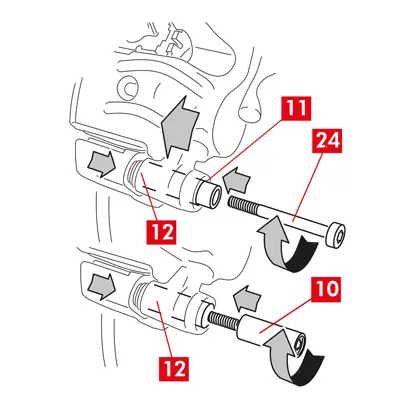
9. Insert and approach the two fixing bolts (points 19 and 20).
10. Tighten the fixing bolt on the disc entry side (point 19) (in forward gear) applying the tightening torque recommended by the vehicle manufacturer.
11. Tighten the second fixing bolt 20 (on the disc exit side) applying the tightening torque recommended by the vehicle manufacturer.
Use the following recommended tightening torques for reference:
| Type of screw | Tightening torque |
| M12x1,25 | 115 Nm |
| M12x1,5 | 125 Nm |
| M14x1,5 | 180 Nm |
| M16x1,5 | 210 Nm |
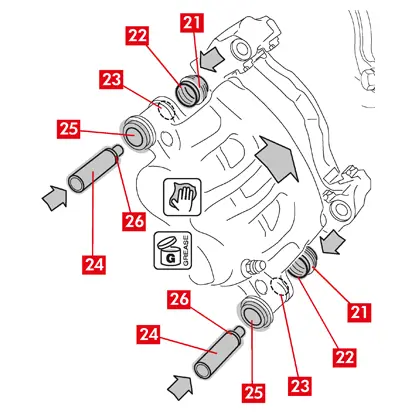
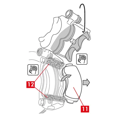
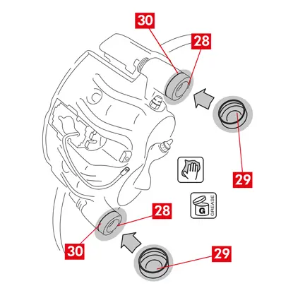
12. Grease the entire inner surface of the covers (point 21) and the contact profile (point 22) with the caliper body evenly.
13. Insert the covers (point 21) in the seats (point 23) on the caliper body.
CAUTION! Using your finger, check the cover has been inserted and seated in the caliper body correctly.
14. Grease the external surface of the bushes (point 24) and their seats (point 25) in the caliper body, insert the bushes in the caliper body from the side opposite the cover.
15. Push the bushes (point 24) until the covers (point 21) fit in their seat (point 26).
16. Remove any excess grease.
17. Fit the caliper body onto the caliper bracket threading through and screwing on the screw or the incorporated bush on the disc exit side (in forward gear).
18. Pull the caliper body (point 27) away from the caliper bracket (point 18) by twisting it around the guiding bush until the pads go into the caliper bracket. Attach the caliper body to the vehicle chassis using appropriate supports.
CAUTION! Do not use the guiding bush seat as a point of attachment.
Fitting the pads
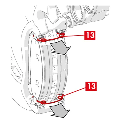
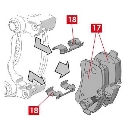
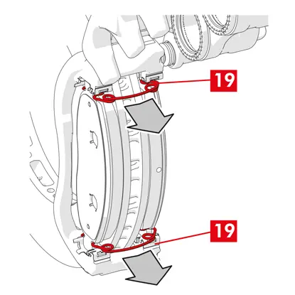
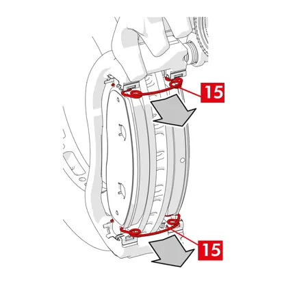
1. Where envisaged, fit the side springs (point 12) in the caliper bracket, exerting the right amount of pressure to attach them securely.
2. In the case of calipers with four springs, always fit the springs with the vanes facing the outside of the caliper bracket.
CAUTION! Observe the correct fitting direction.
WARNING! IF there are any pads with an adhesive side, then new pads must be fitted; follow the instructions provided with the spare pads.
CAUTION! The pad with a wear indicator must be fitted back into the position it was originally in before being disassembled.
3. Reinsert the pads (point 11) in the caliper bracket (point 18); for type B calipers, use a screwdriver to prise open the side springs (point 12).
WARNING! Any arrows stamped on the pads must be pointing in the disc rotation direction.
DANGER! Pads must be inserted with the friction material facing the disc.
WARNING! Any arrows stamped on the pads must be pointing in the disc rotation direction.
DANGER! Pads must be inserted with the friction material facing the disc.
4. Thread the wear indicator cable (point 1) through the dedicated duct as follows:
For type A calipers - in the spring (point 28).
For type B calipers - in the caliper body (point 27).
4. Close the caliper carefully, by twisting the caliper body (point 27) around the screwed-on guiding bush. If there are any pads with an adhesive side, take care not to create contacts between the caliper body and the pad before you have completed the caliper body fitting.
CAUTION! Close the caliper carefully, making sure the protective covers on the bushes are not damaged by knocking against the caliper bracket.
CAUTION! Close the caliper carefully, making sure the protective covers on the bushes are not damaged by knocking against the caliper bracket.
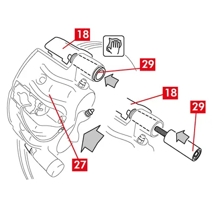
5. Move the caliper body (point 27) towards the caliper bracket (point 18).
6. Reinsert the guiding bush (point 29) in the caliper bracket seat.
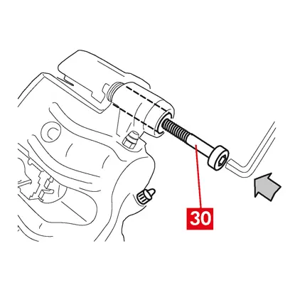
7. Insert and screw in a new screw (point 30), where present.
8. When replacing the caliper on rear wheels with suspension and leaf springs, the caliper body (point 27) must be repositioned on the caliper bracket (point 18), then reinsert both guiding bushes (point 29) and insert and tighten two new screws (point 30), where present.
9. If it is not screwed in yet, tighten the guiding bush fastening screw or the incorporated guiding bush on the disc entry side (in forward gear). Next, tighten the other screw or the other incorporated guiding bush at the same torque.
10. Tighten at the tightening torque specified in the following table:
| Type | Tightening torque | |
| Fastening screw | (M8 – CH6) | 32 ÷ 36 Nm |
| Guiding bush with incorporated screw | (M8 – CH6) | 32 ÷ 36 Nm |
| Guiding bush with incorporated screw | (M10 – CH8) | 65 ÷ 75 Nm |
DANGER! Observe the tightening sequence described; failing to could compromise the proper functioning of the caliper.
11. In the case of residual torque reducing springs (point 31) hook the spring under the plate (point 32) of the pad and hook the underside of the plate on the other pad with the aid of a hollow tip screwdriver.
DANGER! Incorrect attachment of the spring could cause it to spring open.
CAUTION! Observe the correct fitting direction.
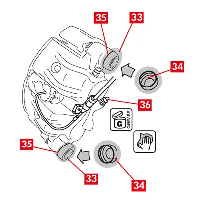
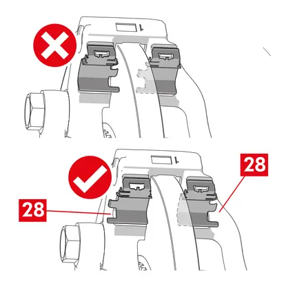
12. Carefully clean the parts (point 33) to make sure they stay in place and fit new protective caps (point 34), greasing their internal surface and the caliper body seat with grease provided in the spare part kit.
13. Turn the protective cap (point 34) so that it adheres fully to the seat (point 35).
14. Reconnect the wear indicator, where present, to the terminal in the vehicle, securing it with a light pressure to the shim present on the caliper and securing any attachments on the chassis.
15. Remove the protective cap from the brake fluid inlet hole (point 36).
16. Reconnect the brake fluid supply line.
17. Remove the spacer you previously placed inside the passenger compartment, thereby releasing the pedal from the brake and allowing the hydraulic circuit to reopen.
18. Open the brake fluid reservoir cap.
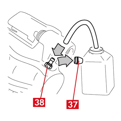
19. Remove the protective cap (point 37) and connect a transparent tube to the bleeder plug (point 38) on the caliper, the ends of which should be placed in a container to collect any fluid.
20. Open the bleeder plug (point 38).
21. Repeatedly press the vehicle brake pedal until brake fluid starts to flow out of the bleeder plug.
22. Holding down the pedal, close the bleeder plug. Release the pedal, wait a few seconds, then repeat the process until fluid without any air bubbles flows out and until the usual resistance and travel of the brake pedal are restored.
23. Tighten the bleeder plug applying the tightening torque specified in the table:
| Bleeder plug | M6x1 | M8x1,25 | M10x1 | M12x1 |
| Tightening torque | 5÷7 Nm | 7÷10 Nm | 17÷20 Nm | 18÷22 Nm |
24. Remove the transparent tube and reposition the protective cap on the bleeder plug.
25. Repeat the bleeding procedure for any other bleeder plugs.
26. After the bleeding process, pull back the pistons in the caliper completely using an appropriate tool (such as a retractor) and then top up the fluid level, as recommended by the manufacturer.
27. Close the brake fluid reservoir cap.
28. With the engine running, apply strong pressure to the vehicle brake pedal and check there are no fluid leaks from the caliper or abnormal pressure losses in the circuit and that the rear brake lights come on.
DANGER! If fluid is leaking from the caliper, repeat all the steps set out in this document to pinpoint the cause and remedy the problem.
29. In the case of calipers with an incorporated parking brake, connect the parking brake cable terminal to its seat on the caliper.
30. Pull and release the cabin parking brake repeatedly.
31. Refit the wheel.
32. If the pads are new, run them in; follow the instructions provided with the spare pads.
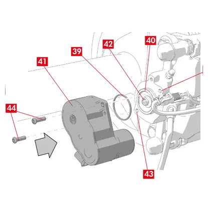
Here the instructions for the replacement of components for commercial vehicle floating calipers (type ECS53 and ECS60) with incorporated electric parking mechanism:
1. Actuator unit
2. Pads
3. Caliper body (without pads and caliper bracket)
4. Caliper bracket
2. Pads
3. Caliper body (without pads and caliper bracket)
4. Caliper bracket
WARNING! Read this document before replacing the spare parts contained in the pack. Only perform those steps required for replacing the spare part or parts contained in the pack.
Replacement procedure
Before commencing replacement, ascertain that the spare parts used for replacement are suitable for the make and model of the vehicle.
WARNING! In the event of an electrical failure, disassemble the actuator unit and pull the piston back, turning the torx screw clockwise with a suitable spanner.
WARNING! In the event of an electrical failure, disassemble the actuator unit and pull the piston back, turning the torx screw clockwise with a suitable spanner.
- Make a note of the position of all the partially or fully disassembled components for correct reassembly.
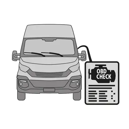
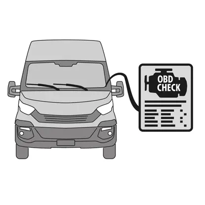
1. Connect the diagnostics tool (On Board Diagnosis - OBD) to the vehicle and put it in maintenance mode procedure as described by the vehicle manufacturer.
CAUTION! Make sure the spare part is compatible with the vehicle software.
2. Remove the wheel.
3. Release the actuator unit electricity supply cable from the cable gland.
4. For caliper type ECS60 loosen and remove the cable gland (point 5).
5. Disconnect the electricity supply cable (point 6) from the actuator unit.
WARNING! The connector may be fitted with a safety latch.
WARNING! The connector may be fitted with a safety latch.
Disassembling the actuator unit
WARNING! Proceed with disassembling the actuator unit only if a separate spare part is available.
1. Loosen the fastening screws (point 7) from the actuator unit (point 1).
2. Remove the actuator unit (point 1).
3. Remove the seal (point 8).
Disassembling the pads
CAUTION! Do not damage any components you intend to re-use.
DANGER! Do not cause the brake fluid supply line to stretch.
DANGER! Do not cause the brake fluid supply line to stretch.
1. Disconnect the wear indicator (point 9), where present, from the terminal in the vehicle, releasing it from the shim that secures it to the caliper and from any attachments on the chassis.
2. Remove the protective cap (point 10) from the secondary bush (forward drive revolution disc exit side).
3. If the cap is made of hard plastic (point 11), prise if off with a screwdriver. Removing the cap will break it.
WARNING! Do not reuse the disassembled hard plastic cap.
4. Loosen and remove the secondary screw (point 12).
5. For caliper type ECS60 use a screwdriver to prise the bush out of the groove to release it from the caliper bracket.
6. Remove the protective cap (point 14) from the primary bush (forward drive revolution disc entry side).
7. Loosen the primary screw (point 15) completely and remove it.
WARNING! Use a screwdriver to prise the guiding bushes out from the grooves.
8. Take out the primary guiding bush (point 16) enough to release it from the caliper bracket.
9. Pull the caliper body (point 3) away from the caliper bracket (point 4) taking care not to cause the brake fluid supply line to stretch.
10. Attach the caliper body to the vehicle chassis using appropriate supports.
CAUTION! Do not use the bush seat as a point of attachment.
11. Remove the pads (point 17) and springs (point 18) without causing any damage so you can reassemble them onto the new caliper.
12. If they are still in position, remove the residual torque reducing springs (point 19).
WARNING! For the correct refitting of the same pads, mark some arrows (where not present) on the pads with a marker to indicate the direction of rotation of the disc.
Disassembling the caliper body
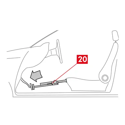
1. Place a spacer (point 20) inside the passenger compartment between the seat and the brake pedal to make sure the pedal remains pressed for the duration of these operations.
AWARNING! This allows the brake hydraulic circuit to be closed, avoiding any brake fluid from leaking.
CAUTION! During all the phases described below, make sure the brake fluid does not come into contact with parts of the vehicle which would be damaged, especially painted parts. Promptly wipe off any accidental brake fluid splashes or leaks with kitchen towel and clean with water.
2. Loosen the supply line (point 21) on the caliper enough to be able to screw it off completely by hand, as this will avoid any brake fluid leaking out.
3. Detach the supply line (point 21) completely from the caliper body.
4. Promptly wipe off any brake fluid leaks.
5. Keep the supply line raised to prevent any fluid leaks.
6. Pull away the caliper body (point 3).
Disassembling the caliper bracket
CAUTION! During disassembly, keep the caliper bracket in position to avoid it accidentally dropping.
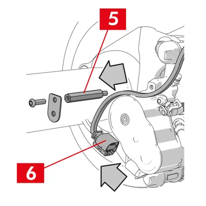
1. Loosen the fastening screws (point 22).
2. Remove the caliper bracket (point 4) from the hub bracket.
Fitting procedure
Reassemble the new spare components.
1. Thoroughly clean all the components to be fitted (whether new or removed previously), the bush seats and the spring seats using appropriate products (e.g. a damp cloth).
DANGER! Make sure the components are intact, replace them with new ones if damaged.
2. Clean the mounting faces (point 23) on the hub bracket.
3. Clean the braking surfaces (point 24) on the disc using a degreasing product (e.g. Solvent SE47).
Fitting the caliper bracket
1. Position the new caliper bracket (point 25) on the hub bracket.
2. Insert and tighten the fastening screws (point 26) at the tightening torque recommended by the vehicle manufacturer.
Fitting the pads and caliper body
1. Reinsert the springs (point 27), placing them the right way round in their seats.
2. For caliper type ECS52 with four springs, always fit the springs with the vanes (point 28) facing the outside of the caliper bracket.
WARNING! IF there are any pads with an adhesive side, then new pads must be fitted; follow the instructions provided with the spare pads.
CAUTION! The pad with a wear indicator must be fitted back into the position it was originally in before being disassembled.
DANGER! Pads must be inserted with the friction material facing the disc.
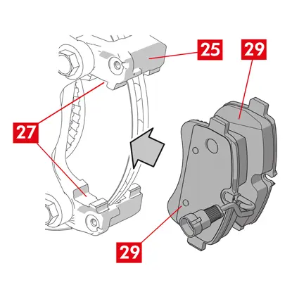
3. Reinsert the pads (point 29) in the caliper bracket (point 25); use a screwdriver to prise open the side springs (point 27).
4. In the case of residual torque reducing springs (point 30) hook the spring under the plate (point 31) of the pad and hook the underside of the plate on the other pad with the aid of a hollow tip screwdriver.
DANGER! Incorrect attachment of the spring could cause it to spring open.
DANGER! Incorrect attachment of the spring could cause it to spring open.
CAUTION! Observe the correct fitting direction.
CAUTION! If the caliper body is new, do not disassemble the protective cap from the fluid inlet hole on the new caliper until you connect the supply line to it.
6. Position the caliper body (point 32) by inserting it in the disc, so that the guiding bushes coincide with the holes on the caliper bracket.
CAUTION! Do not damage the covers.
7. Push the guiding bushes (point 33) into their seats on the caliper bracket.
8. Insert and tighten the screws (point 34) using a tightening torque of 32 ÷ 36 Nm.
9. Position the caps (point 35).
CAUTION! Before removing the protective cap, leave the supply point as high as possible, making sure none of the brake fluid inside the caliper leaks out.
10. Reconnect the wear indicator cable, where present, to the terminal in the vehicle, securing it with a light pressure to the shim on the caliper, where present, and securing any attachments on the chassis.
Connecting the brake fluid supply line
1. Remove the protective cap (point 36) from the brake fluid inlet hole.
2. Reconnect the brake fluid supply line (point 21).
3. Remove the spacer you previously placed inside the passenger compartment, thereby releasing the pedal from the brake and allowing the circuit to reopen.
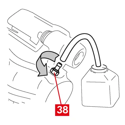
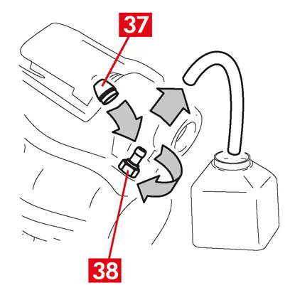
4. Remove the protective cap (point 37) from the bleeder plug (point 38).
5. Connect a transparent tube to the bleeder plug (point 38) on the caliper, the ends of which should be placed in a container to collect any fluid.
6. Open the bleeder plug (point 38).
7. Repeatedly press the vehicle brake pedal until brake fluid starts to flow out of the bleeder plug.
8. Holding down the pedal, close the bleeder plug. Release the pedal, wait a few seconds, then repeat the process until fluid without any air bubbles flows out and until the usual resistance and travel of the brake pedal are restored.
9. Tighten the bleeder plug (point 38) applying the tightening torque specified in the following table:
| Bleeder type | M10x1 |
| Tightening torque | 12÷16 Nm |
10. Remove the transparent tube.
11. Repeat the bleeding procedure for any other bleeder plugs.
12. Reposition the protective cap (point 37).
13. After the bleeding process, pull back the pistons in the caliper completely using an appropriate tool (such as a retractor) and then top up the fluid level, as recommended by the manufacturer.
14. With the engine running, apply strong pressure to the vehicle brake pedal and check there are no fluid leaks from the caliper or abnormal pressure losses in the circuit and that the rear brake lights come on.
DANGER! If fluid is leaking from the caliper, repeat all the steps set out in this document to pinpoint the cause and remedy the problem.
Fitting the actuator unit
WARNING! The actuator unit may be supplied already fitted to the caliper body.
Reassemble the new spare components.
- Clean any components you removed previously before reassembling them.
CAUTION! Always use new screws with thread locker. Always fit a new seal.
DANGER! Make sure the components are intact, replace them with new ones if damaged
1. Clean the contact surface on the caliper and on the actuator unit.
2. Remove any thread locker residue from threaded screw seats.
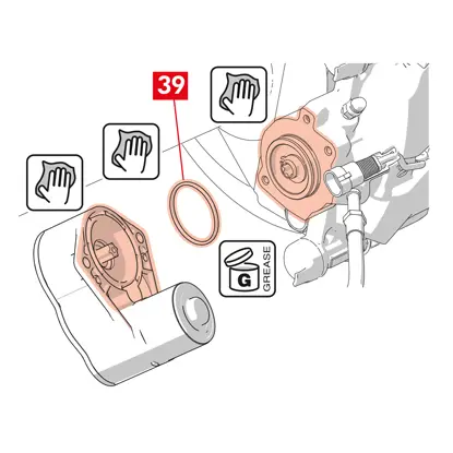
3. Clean and lubricate the seal (point 39) with the grease supplied.
4. Lubricate the internal diameter of the actuator unit coupling with the grease supplied.
WARNING! EUH210 - Safety data sheet available upon request.
WARNING! EUH208 - Contains N-alkylated benzotriazole. May cause an allergic reaction.
5. Position the seal (point 39) in its seat (point 40) on the caliper body.
6. Fit the actuator unit (point 41) on the torx screw (point 42) on the caliper body.
7. Turn the actuator unit (point 41) so that the holes (point 43) of the fastening screws (point 44) coincide with their original fitting position.
CAUTION! Avoid pinching the seal (point 39) when fitting the actuator unit on the caliper body.
8. Insert and tighten the fastening screws (point 44) at a tightening torque of 7 ÷ 10 Nm.
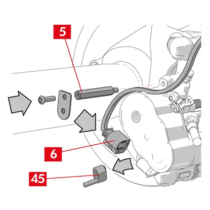
9. Remove the protective cap (point 45), where present, and connect the electrical supply cable (point 6).
10. Where removed previously, screw on the cable gland (point 5).
11. Secure the actuator unit electricity supply cable (point 6) to the cable gland (point 5).
Final phases
1. Refit the wheel.
2. Perform the reset procedure (Assembly check).
3. If necessary, reset the counters (Reset Internal Counters) as prescribed by the vehicle manufacturer.
4. If required by the vehicle manufacturer, run in the pads.
5. Disconnect the diagnostics device. (On Board Diagnosis – OBD).
Here the instructions for the replacement of the caliper body for floating calipers with 2 or 4 side springs and residual torque reducing springs.
When replacing only the fastening screws, only refer to the relevant parts.
Replacement procedure
Before commencing replacement, ascertain that the spare parts used for replacement are suitable for the make and model of the vehicle.
- Make a note of the position of all the partially or fully disassembled components for correct reassembly.
- Remove the wheel.
For ECS calipers
WARNING! In the event of an electrical failure, disassemble the actuator unit (point 5) and pull the piston back, turning the torx screw clockwise with a suitable spanner
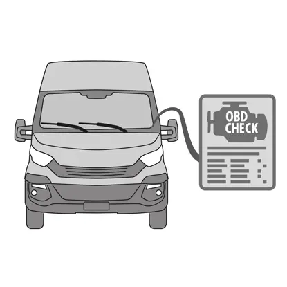
1. Connect the diagnostics tool (On Board Diagnosis - OBD) to the vehicle and put it in maintenance mode procedure as described by the vehicle manufacturer.
CAUTION! Without this operation, the piston cannot be pulled back with the retractor or another suitable tool.
CAUTION! Make sure the spare part is compatible with the vehicle software.
2. Disconnect the electricity supply cable (point 2) from the actuator unit.
WARNING! The connector may be fitted with a safety latch.
For all types of calipers
1. For calipers with a parking brake, detach the control cable (point 3) from the caliper.
2. Disconnect the wear indicator (point 4), where present, from the terminal in the vehicle, releasing it from the shim (point 5) that secures it to the caliper and from any attachments on the chassis.
3. Remove the protective caps (point 6) from the guiding bushes.
4. If the cap has a lip (point 7), snap off the cap by pulling on the lip (point 7) with your fingers.
5. If the cap is made of hard plastic (point 8), prise if off with a screwdriver. Removing the cap will break it.
WARNING! Do not reuse the disassembled hard plastic cap.
CAUTION! The guiding bush to disassemble must be the one that allows the caliper body to turn without causing the brake fluid supply line to stretch.
WARNING! There are two types of guiding bushes: with separate screw, with incorporated screw.
6. Loosen and completely remove the screw (point 9) or incorporated guiding bush (point 10) using a spanner.
7. In the case of a non-incorporated guiding bush (point 11), pull the guiding bush out of the caliper bracket (point 12) prising it out of its seat with a screwdriver.
8. When replacing the caliper on rear wheels with suspension and leaf springs, both the guiding bushes 11 must be removed to separate the caliper body (point 13) completely from the caliper bracket (point 12).
WARNING! If there are any brake pads glued to the caliper, detach them using a screwdriver and take care not to damage any rubber parts of the caliper.
DANGER! Opening the caliper body may cause the residual torque reducing springs to spring open.
9. Pull the caliper body (point 13) away from the caliper bracket (point 12) by twisting it around the other guiding bush until the pads (point 14) come out of the caliper bracket. Attach the caliper body to the vehicle chassis using appropriate supports. Do not use the bush seat as a point of attachment.
11. Remove the pads (point 14) without causing any damage.
12. Use a marker to mark the direction of rotation of the disc on the pads to avoid reassembling them incorrectly.
14. If they are still in position, remove the residual torque reducing springs (point 15).
15. Place a spacer (point 16) inside the passenger compartment between the seat and the brake pedal to make sure the pedal remains pressed for the duration of these operations.
WARNING! This allows the brake hydraulic circuit to be closed, avoiding any brake fluid from leaking.
CAUTION! During all the phases described below, make sure the brake fluid does not come into contact with parts of the vehicle which would be damaged, especially painted parts. Promptly wipe off any accidental brake fluid splashes or leaks with kitchen towel and clean with water.
CAUTION! During all the phases described below, make sure the brake fluid does not come into contact with parts of the vehicle which would be damaged, especially painted parts. Promptly wipe off any accidental brake fluid splashes or leaks with kitchen towel and clean with water.
16. Loosen the supply line (point 17) on the caliper enough to be able to screw it off completely by hand, as this will avoid any brake fluid leaking out.
17. Loosen completely and remove the screw (point 9) or incorporated guiding bush (point 10).
18. In the case of a non-incorporated guiding bush (point 11), pull the guiding bush out of the caliper bracket (point 12) prising it out of its seat with a screwdriver.
19. Pull the caliper body (point 13) away from the caliper bracket (point 12) taking care not to cause the brake fluid supply line to stretch.
20. Detach the supply line (point 17) completely from the caliper body.
21. Promptly wipe off any brake fluid leaks.
22. Keep the supply line raised to prevent any brake fluid leaks.
23. Pull away the caliper to be replaced.
24. In the case of calipers with an incorporated parking brake, disconnect the parking brake cable from its seat on the caliper.
25. Clean the braking surfaces on the disc using a degreasing product (e.g. Solvent SE47).
Fitting the pads
CAUTION! If there are any pads with an adhesive side, then new pads must be fitted; follow the instructions provided with the spare pads.
1.Check the springs are correctly positioned. In the case of calipers with four springs, make sure the vanes are always facing the outside of the caliper bracket.
CAUTION! Incorrect spring positioning could possibly cause injury.
2. Insert the pads (point 14) in the caliper bracket (point 12). Use a screwdriver to press the side springs.
WARNING! Any arrows stamped on the pads must be pointing in the disc rotation direction.
DANGER! Pads must be inserted with the friction material facing the disc.
CAUTION! The pad with a wear indicator must be fitted back into the position it was originally in before being disassembled.
WARNING! Any arrows stamped on the pads must be pointing in the disc rotation direction.
DANGER! Pads must be inserted with the friction material facing the disc.
CAUTION! The pad with a wear indicator must be fitted back into the position it was originally in before being disassembled.
3. Where present, attach the wear indicator terminal (point 20) to the pad opposite the pistons, replacing it if necessary.
CAUTION! When attaching the wear indicator terminal, make sure the most protruding part is facing the friction surface on the pad.
CAUTION! When attaching the wear indicator terminal, make sure the most protruding part is facing the friction surface on the pad.
Fitting the caliper body
CAUTION! For calipers with a parking brake - while the caliper body is disassembled from the brake disc and/or the brake pads are absent, do not move the piston either hydraulically or using the lever as this could damage the spring and/or cause the brake fluid to leak.
1. On the caliper bracket, wipe the fitting areas (point 21) with the caliper body (guide seats) with a damp cloth.
CAUTION! Do not use products which could damage the protective covers, such as nitro-tetrachloroethylene thinner, petrol, etc.
2. Clean and uniformly grease the entire internal surface of the covers, the external surface of the guiding bushes and their seats in the caliper body.
3. Position the new caliper body (point 22), setting one of the two guiding bushes (point 10) in the seat on the caliper bracket (point 12).
CAUTION! Don’t remove the protective cap from the brake fluid inlet hole until the tube is connected definitively.
CAUTION! Don’t remove the protective cap from the brake fluid inlet hole until the tube is connected definitively.
4. In the case of a non-incorporated guiding bush (point 11), fit and tighten a new screw (point 23).
5. Close the caliper carefully, by twisting the caliper body (point 22) around the seated guiding bush.
CAUTION! Close the caliper carefully, making sure the protective covers on the bushes are not damaged by knocking against the caliper support. Replace the covers if necessary.
WARNING! If there are any pads with an adhesive side, take care not to create contacts between the body and the pad before you have completed the caliper body fitting.
6. Thread the wear indicator probe (point 20) through the dedicated hole in the caliper body (point 22).
7. Reinsert the other guiding bush (point 10) in the caliper bracket seat (point 12).
8. In the case of a non-incorporated guiding bush (point 11), fit and tighten a new screw (point 24).
CAUTION! When replacing the caliper bracket on rear wheels with suspension and leaf springs, the caliper body must be repositioned on the caliper bracket, then reinsert both guiding bushes and insert and tighten two new screws.
9. Tighten the guiding bush fastening screw or the incorporated guiding bush (point 24) on the disc entry side (in forward gear). Next, tighten the other screw or the incorporated guiding bush (point 25) at the same torque.
10. Tighten at the tightening torque specified in the following table:
| Type | Tightening torque | |
| Fastening screw | (M8 – CH6) | 32 ÷ 36 Nm |
| Guiding bush with incorporated screw | (M8 – CH6) | 32 ÷ 36 Nm |
| Guiding bush with incorporated screw | (M10 – CH8) | 65 ÷ 75 Nm |
DANGER! Observe the tightening sequence described; failing to could compromise the proper functioning of the caliper.
11. In the case of residual torque reducing springs (point 26) hook the spring under the plate (point 27) of the pad and hook the underside of the plate on the other pad with the aid of a hollow tip screwdriver.
DANGER! Incorrect attachment of the spring could cause it to spring open.
CAUTION! Observe the correct fitting direction.
12. Carefully clean the part (point 28) to make sure it stays in place and fit new protective caps (point 29), greasing their internal surface and the caliper body seat with grease provided in the spare part kit.
WARNING! EUH210 - Safety data sheet available upon request.
WARNING! EUH208 - Contains N-alkylated benzotriazole. May cause an allergic reaction.
WARNING! EUH208 - Contains N-alkylated benzotriazole. May cause an allergic reaction.
13. Turn the protective caps (point 29) so that they adhere fully to the seat (point 30).
14. Reconnect the wear indicator, where present, to the terminal in the vehicle, securing it with a light pressure to the shim present on the caliper and securing any attachments on the chassis.
15. Remove the protective cap from the brake fluid inlet hole.
16. Reconnect the brake fluid supply line.
17. Remove the spacer you previously placed inside the passenger compartment, thereby releasing the pedal from the brake and allowing the circuit to reopen.
For calipers with a parking brake
CAUTION! Before assembling the piston with the pads, make sure the caliper bracket, pads and disc are present.
- Use the lever to assemble the piston with the pads.
CAUTION! Hydraulic operation is only permitted when the piston is less than 1 mm from the pads.
For all types of calipers
1. Connect a transparent tube to the bleeder plug (point 31) on the caliper, the ends of which should be placed in a container to collect any fluid.
2. Open the bleeder plug (point 31).
3. Repeatedly press the vehicle brake pedal until brake fluid starts to flow out of the bleeder plug.
4. Holding down the pedal, close the bleeder plug. Release the pedal, wait a few seconds, then repeat the process until fluid without any air bubbles flows out and until the usual resistance and travel of the brake pedal are restored.
5. Tighten the bleeder plug (point 31) applying the tightening torque specified in the table:
| Bleeder plug | M6x1 | M8x1,25 | M10x1 | M12x1 |
| Tightening torque | 5÷7 Nm | 7÷10 Nm | 17÷20 Nm | 18÷22 Nm |
6. Remove the transparent tube.
7. Repeat the bleeding procedure for any other bleeder plugs.
8. After the bleeding process, pull back the pistons in the caliper completely using an appropriate tool (such as a retractor) and then top up the fluid level, as recommended by the manufacturer.
9. Close the brake fluid reservoir cap.
10. With the engine running, apply strong pressure to the vehicle brake pedal and check there are no fluid leaks from the caliper or abnormal pressure losses in the circuit and that the rear brake lights come on.
DANGER! If fluid is leaking from the caliper, repeat all the steps set out in this document to pinpoint the cause and remedy the problem.
For calipers with a parking brake
- Reconnect the wear indicator, where present, to the terminal in the vehicle, securing it with a light pressure to the shim present on the caliper and securing any attachments on the chassis.
- Restore the correct tension to the control cable.
- Repeatedly operate the parking brake lever in the vehicle cab until the usual stroke has been re-established.
For ECS calipers

1. Remove the protective cap (where present) and connect the electrical supply cable (point 2).
2. Perform the reset procedure (Assembly check).
3. If necessary, reset the counters (Reset Internal Counters) as prescribed by the vehicle manufacturer.

4. If required by the vehicle manufacturer, run in the pads.
5. Disconnect the diagnostics device (On Board Diagnosis - OBD).
For all types of calipers
1. Refit the wheel.
2. If the pads are new, run them in; follow the instructions provided with the spare pads.
2. If the pads are new, run them in; follow the instructions provided with the spare pads.
Warranty limitations
This warranty covers all the conformity defects occurring within two years from delivery of the good. The consumer is required to report to the seller the conformity defect within two months from the date of discovery of the said defect, without prejudice to the fact that the limitations period for taking action aimed at seeking redress for the defect is twenty-six months from delivery of the good. In the event of a conformity defect, the user has the right to repair or replacement of the good, or to an appropriate price reduction or termination of the contract, as established by art. 130 of the Consumer Code, where applicable.
This warranty constitutes the only warranty provided in relation to this product and replaces any other warranties, both verbal and written.
In the event of the occurrence of defects, the user is required:
- Under penalty of invalidation, to notify the manufacturer and distributor in writing within sixty days; at the same time, the user shall provide a description of the defect found on the Product or on the parts returned, and a proof of purchase of the original user which identifies both the Product and the date of purchase (whether purchased retail or sold by a distributor as part of the Product installation);
- To send the Product assumed to be defective to Brembo S.p.A. to the headquarters in via Brembo 25 -24035 Curno (BG) - Italy, via the distribution chain
The warranty does not operate for:
- Damage to the Product caused, partly or entirely, by incorrect use, accident, fire, chemical corrosion, use for purposes other than those scheduled, illicit use, use on a model different from the one scheduled, incorrect installation, installation contrary to the directions of the Manufacturer, or lack of maintenance on the Product as prescribed by the Manufacturer in the instructions provided;
- Complaints connected with comfort, the presence of noise, vibrations or harsh riding characteristics.
The Product has been designed and produced for the specific model and use indicated in the Brembo catalogues and/or by the Brembo product distributors, both available on the Brembo website (www.brembo.com). The Product shall be used according to the laws in force in the states and/or in the countries where the vehicle on which the Product is installed is used, including, but without limitation to, observance of the regulations of the Highway Code and after obtaining any authorisation/approval, permit or licence required by the state and/or country.
For products sold in the territories of the European Union member states, these Warranty Limitations operate in compliance with the provisions of the Directive 85/374/EEC of the Council of 25th July 1985.
For products sold in the territories of the United States, these Warranty Limitations operate in compliance with any applicable federal or state law.
For products sold in the territories of the United States, these Warranty Limitations operate in compliance with any applicable federal or state law.
General and safety information
This Brembo product has been designed to comply with all applicable safety standards. Products are not intended to be used differently from the specific use for which they have been designed and manufactured. Use for any other purpose, or any modification to or tampering with the Product can affect the performance of the Product and may render the Product unsafe.
Such modification or improper use will void the Limited Warranty, and may subject the individual so using the Product to liability for bodily injury or property damage to others.
In these instructions, the “DANGER!” warning means procedures which, if not observed, have a high degree of probability that they will cause serious injury or even death. “CAUTION”” means procedures which, if not observed, could result in physical damage whereas “WARNING!” means procedures which, if not observed, could possibly cause damage to the vehicle.
DANGER!
Before commencing replacement, ascertain that the spare parts are suitable for the make and model of the vehicle. This Product is vital to the safe operation of the vehicle on which it is installed, and it is intended to be installed only by a skilled, qualified individual who has been trained and/or is experienced in the installation and use for which the Product is intended.
The installer must be equipped with the proper tools of his trade, and with the knowledge and experience to deal with vehicle repairs. Improper or incorrect installation, whether caused by a failure to follow these Instructions faithfully and completely or otherwise, will void the Limited Warranty and could subject the installer to liability in the event of personal injury or property damage.
Brembo shall not be liable for any damage or injury caused to or by any person operating a vehicle on which a replacement product has been improperly installed.
CAUTION!
Replaced parts must be disposed of in accordance with the law.
It is vital to avoid sharply striking and/or damaging the Product, its parts and its components, as this can impair their efficiency and may cause them to malfunction. If necessary, replace any damaged part or component. To avoid injury we recommend the following:
- Use suitable equipment to prevent the inhalation of dust raised during cleaning of the parts.
- Always wear gloves during disassembly and assembly of components with sharp edges.
- Do not allow skin surface to make direct contact with the friction material of pads and brake shoes since this could cause abrasions.
- Do not introduce your hands in the seat of the pads when removing the caliper pistons using compressed air as this involves the risk of crushing your hands.
- Avoid direct contact with the brake fluid as it can cause irritation to the skin and eyes. In the event of accidental contact, clean thoroughly in accordance with the vehicle or brake fluid manufacturer’s instructions.
- Do not subject the electrical components to electrostatic charges or to impact which could damage the plastic parts.
- Protect the disassembled electrical components from humidity.
- Ensure correct connection of any electrical contacts, checking that the warning lights come on. If they do not, non-operation of the warning lights can cause a reduction in efficiency of the braking system, or brake signalling failure.
- Avoid contact of grease and other lubricants with the braking surfaces of the brake disc, drum, pads and shoes as this could affect the efficiency of the braking system and cause serious physical damage.
- Do not use sharp tools to fit rubber components as this could damage them. Make sure any damaged parts are replaced.
Garanti
Bu Ürünün, üreticinin spesifikasyonlarına uygun olduğunu ve malzeme ve işçilik ayıpları içermediğini garanti ederiz. Garanti süresi, satın alma tarihinden itibaren iki yıl veya kanunların öngördüğü daha uzun bir süre ile sınırlıdır. Garanti süresi, satın alma tarihinden itibaren iki yıl veya kanunların öngördüğü daha uzun bir süre ile sınırlıdır. Bir kusur tespit edilmesi halinde, tespit edilmesini müteakip 60 gün içinde ve satın alma tarihinden itibaren iki yıl içinde bildirilmelidir. Kusurun doğrulanması ve garanti kapsamına girmesi halinde, Ürün, tamir edilir veya yeni ya da tamamen yenilenmiş bir Ürün ile değiştirilir. Kısmen veya tamamen yanlış kullanım, yangın, kimyasal aşınma, kötüye kullanım veya kullanım amacı dışında kullanım, uygun olmayan bir model üzerinde kullanım, yanlış montaj veya üretici tarafından belirtilenin haricinde montaj ya da Ürünün Üretici tarafından talimatlarda belirtilen şekilde bakımının yapılmamasından kaynaklanan hasarlar, garanti kapsamı dışındadır.
Sormak istediğiniz başka bir şey var mı?
Brembo teknik destek ekibiyle iletişime geçin. Teknisyenlerimiz sizinle en kısa zamanda iletişime geçecek.