


승용차 및 경상용차의 브레이크 캘리퍼 교체 지침
모든 지침을 주의 깊게 읽고 따라주십시오. 브레이크 캘리퍼 팩에서도 동일한 지침을 찾을 수 있습니다. 전체 제품 수명 주기 동안 지침을 보관하는 것을 잊지 마십시오. 차량을 판매할 경우 새 소유자에게 지침을 인도하십싵오.
이 장착 지침은 표준 수리 작업에 대한 지침이며, 다른 브레이크 시스템에 적용될 수 있는 특별한 기능을 고려하지 않았습니다. 차량 및 브레이크 시스템 제조업체에서 발행한 특별 지침을 자세히 따라야 합니다.
이 문서는 다음 캘리퍼 교체에 대한 지침을 제공합니다.
1. 싱글 디스크 브레이크 캘리퍼
2. 듀얼 디스크 고정 캘리퍼
3. 방사형 마운트 패드가 있는 플로팅 캘리퍼, 유형 2x60/68.
2. 듀얼 디스크 고정 캘리퍼
3. 방사형 마운트 패드가 있는 플로팅 캘리퍼, 유형 2x60/68.
이 지침의 모든 정보는 달리 명시되지 않는 한 세 가지 유형의 캘리퍼에 모두 적용됩니다.
교체 절차
교체를 시작하기 전에 교체에 사용되는 예비 부품이 차량 제조사 및 모델에 적합한지 확인하십시오.
- 휠을 제거합니다.
- 올바른 재조립을 위해 부분적으로 또는 완전히 분해된 모든 구성품의 위치를 기록해 두십시오.
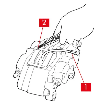
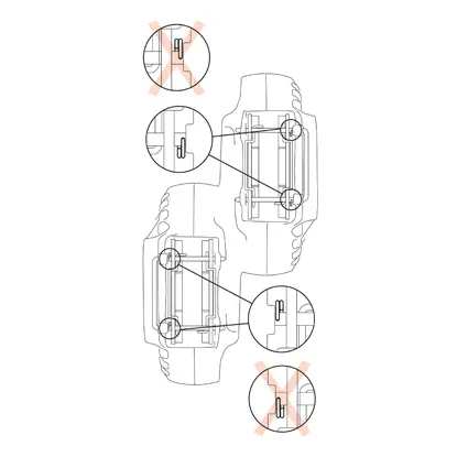
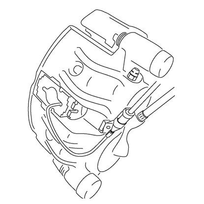
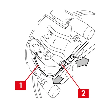
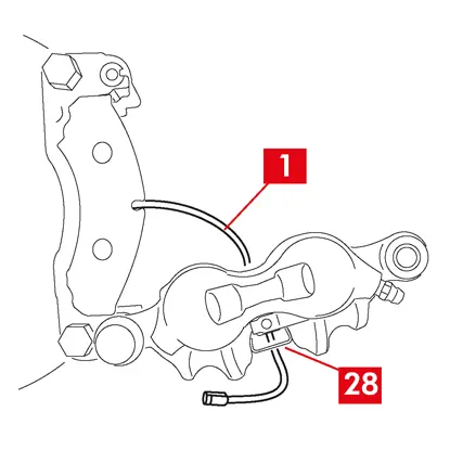
1. 마모 표시기 케이블(포인트 1)이 있는 경우 차량의 단자에서 분리하여 섀시 및 캘리퍼의 모든 부착물에서 분리합니다.
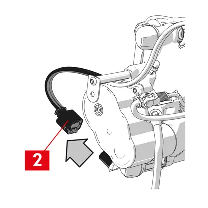
2. 안전 분할 핀(포인트 2)이 장착된 모델의 경우 플라이어를 사용하여 클립을 제거합니다.
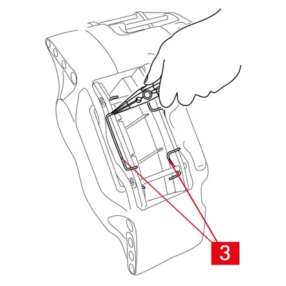
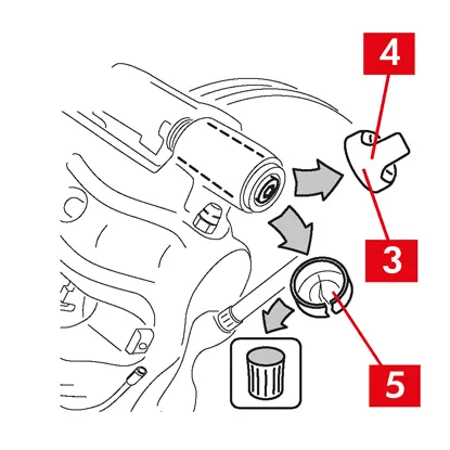
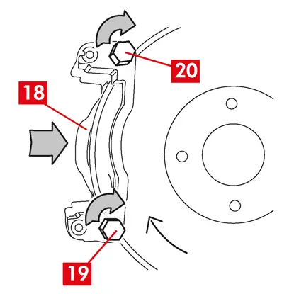
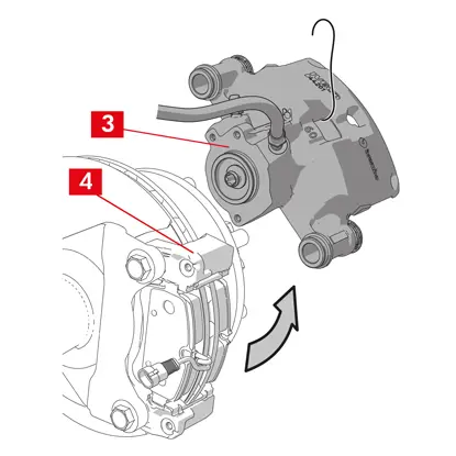
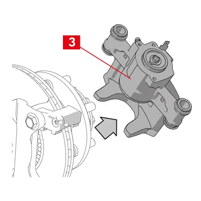
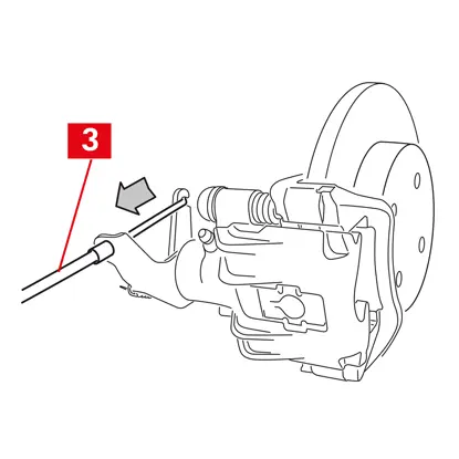
3. 듀얼 디스크 캘리퍼의 경우 플라이어를 사용하여 스프링(포인트 3)을 제거합니다.
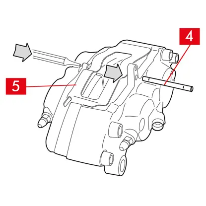
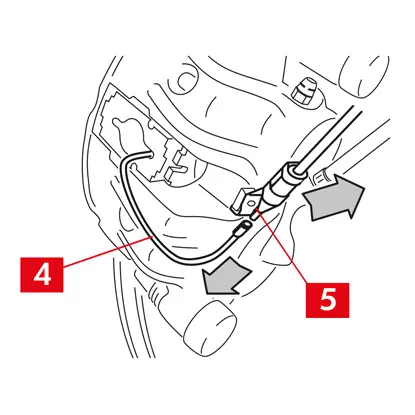
4.망치와 핀 드라이버를 사용하여 핀(포인트 4)을 당겨 빼냅니다. 스프링(포인트 5)이 제자리에 있는지 확인하면서 손으로 완전히 당겨 빼냅니다.

5. 스프링(포인트 5)을 제거합니다. 오일 수위를 확인합니다. 브레이크 오일 저장소 캡을 엽니다.
주의! 아래에 설명한 피스톤을 뒤로 당기는 단계로 인해 저장소의 브레이크 오일 수위가 상승합니다. 수위가 맞지 않으면 브레이크 오일이 누출되어 차량의 도장된 부분이 손상될 수 있으므로 주의하십시오.
고정 캘리퍼 A B형
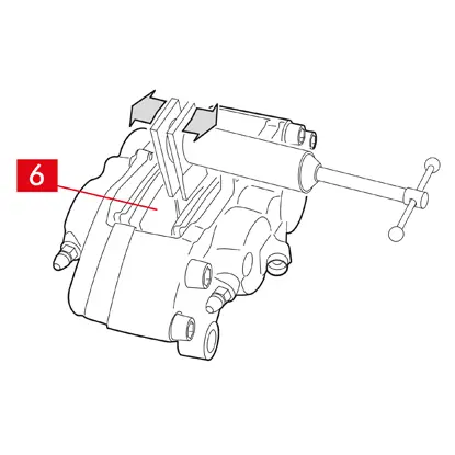
1. 리트랙터나 기타 적절한 도구를 사용하여 피스톤을 살짝 당겨서 패드(포인트 6)를 누릅니다.
피스톤을 뒤로 당기면 캘리퍼가 디스크에서 풀릴 수 있어야 합니다.
2. 캘리퍼의 디자인이 허용하는 경우 패드를 제거합니다. 그렇지 않으면 캘리퍼를 분해한 후 제거합니다. 패드를 재사용하려면 마커로 디스크의 회전 방향을 표시합니다.
플로팅 캘리퍼 C형
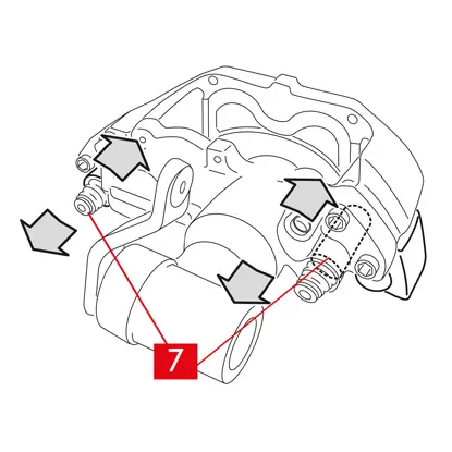
1. 패드를 꺼내는 동시에 캘리퍼 본체를 가이드 부시(포인트 7)에서 앞뒤로 밀어서 빼냅니다. 캘리퍼 본체를 밀면 패드가 디스크에서 약간 떨어져서 쉽게 제거할 수 있습니다.
디스크 마모로 인해 생긴 움푹 들어간 부분이 패드를 빼내는 데 방해가 되는 경우 캘리퍼 본체를 분해합니다.
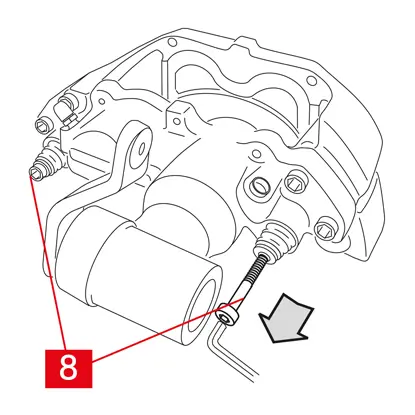
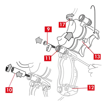
1. 스패너를 사용하여 나사(포인트 8)를 분해합니다.
2. 드라이버를 사용하여 전용 시트에서 가이드 부시를 들어 올립니다.
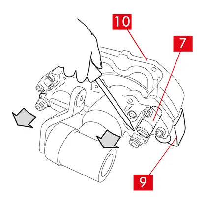
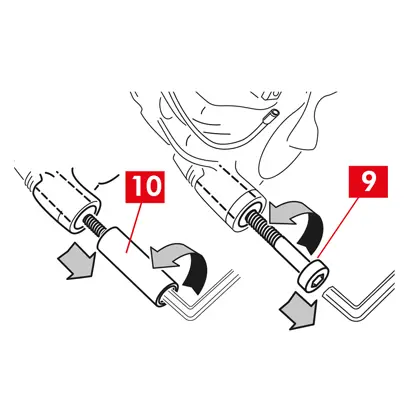
3. 캘리퍼 브래킷(포인트 9)에서 분리할 수 있을 만큼 가이드 부시(포인트 7)를 빼냅니다.
4. 캘리퍼 본체(포인트 10)를 캘리퍼 브래킷(포인트 9)에서 완전히 분리한 후 S자형 고리를 사용하여 차량 섀시에 걸어 놓습니다.
5. 패드를 꺼냅니다.
6. 패드를 재사용하려면 마커로 디스크의 회전 방향을 표시합니다.
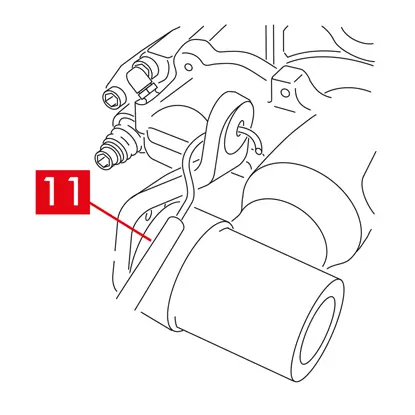
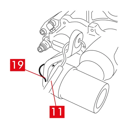
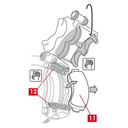
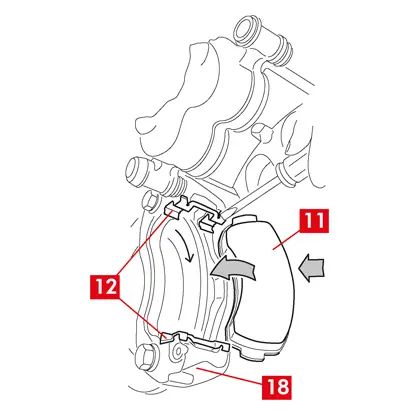
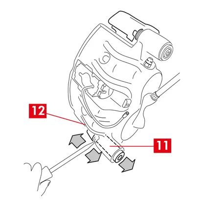
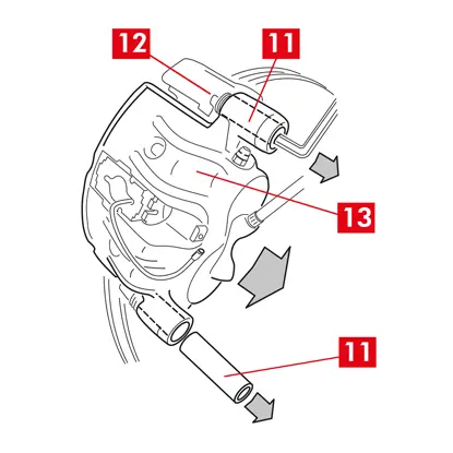
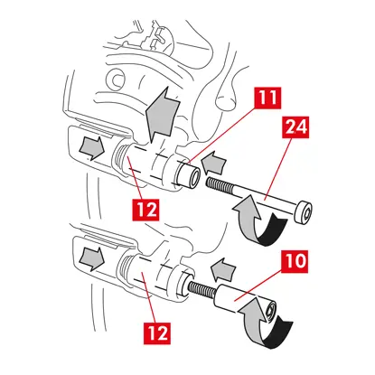
7. 후방 캘리퍼(주차 메커니즘 포함)의 경우 주차 제어 케이블(포인트 11)을 분리합니다.
위험! 브레이크 오일 라인은 늘어지지 않고 느슨한 상태를 유지해야 합니다. 라인이 늘어나면 끊어져 브레이크 오일이 새어 나올 수 있습니다.
모든 유형의 캘리퍼
1. 브레이크 오일 저장소 캡을 닫습니다.
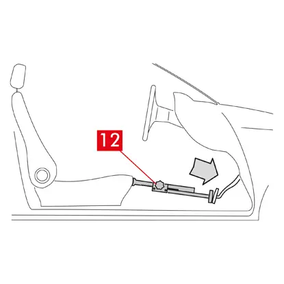
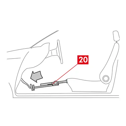
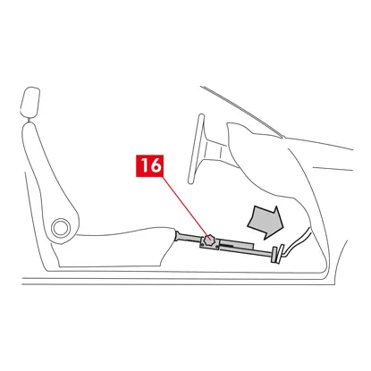
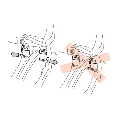
2. 승객실 내부의 좌석과 브레이크 페달 사이에 스페이서(포인트 12)를 배치하여 작업을 수행하는 동안 페달이 계속 눌려 있도록 합니다.
경고! 이렇게 하면 브레이크 유압 회로가 닫혀 브레이크 오일이 새는 것을 방지할 수 있습니다.
주의! 아래에 설명된 모든 단계에서 브레이크 오일이 손상될 수 있는 차량 부품, 특히 도장된 부품에 닿지 않도록 주의하십시오.
경고! 이렇게 하면 브레이크 유압 회로가 닫혀 브레이크 오일이 새는 것을 방지할 수 있습니다.
주의! 아래에 설명된 모든 단계에서 브레이크 오일이 손상될 수 있는 차량 부품, 특히 도장된 부품에 닿지 않도록 주의하십시오.
실수로 오일이 튀거나 새면 즉시 키친타월로 닦아내고 물로 닦아내십시오.
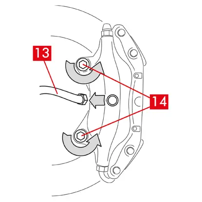
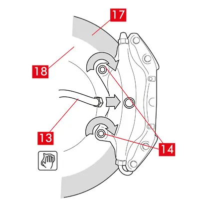
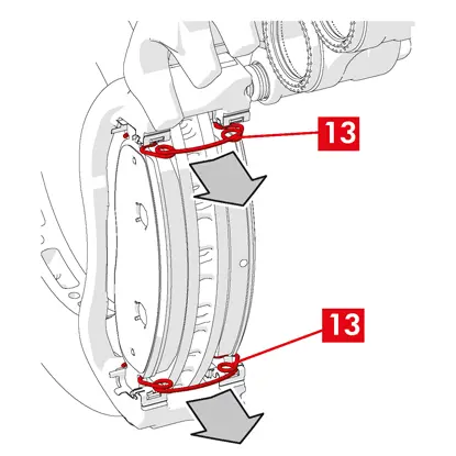
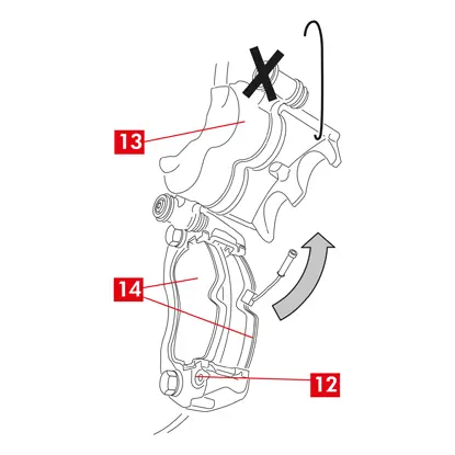
3. 캘리퍼의 공급 라인(포인트 13)을 손으로 완전히 풀 수 있을 정도로 느슨하게 하되 브레이크 오일이 새지 않도록 주의합니다.
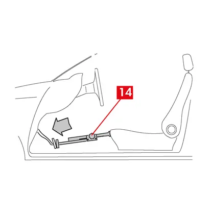
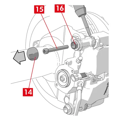
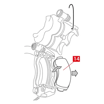
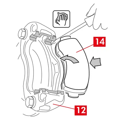
4. 개방형 스패너를 사용하여 고정 나사(포인트 14)를 풀고 차축에서 캘리퍼를 분리합니다.
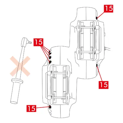
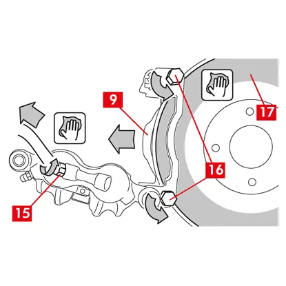
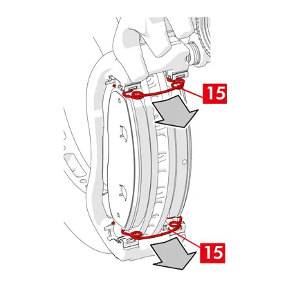
5. 주의! 듀얼 디스크 캘리퍼의 경우 차축 고정 나사만 분해하십시오. 하프 캘리퍼를 연결하는 나사(포인트 15)는 분해하지 마십시오.
6. 캘리퍼에서 공급 라인(포인트 13)을 분리합니다.
7. 브레이크 오일이 새는 경우 즉시 닦아냅니다.
8. 실수로 오일이 새지 않도록 공급 라인을 높게 유지합니다.
9. 교체할 캘리퍼를 당겨서 빼냅니다.
9. 교체할 캘리퍼를 당겨서 빼냅니다.
장착 절차
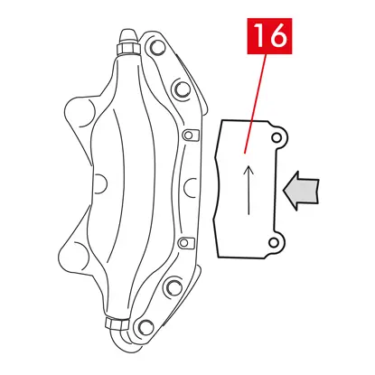
1.새 캘리퍼에 패드(포인트 16)를 삽입합니다.
경고! 패드에 찍힌 화살표가 디스크 회전 방향을 가리키고 있어야 합니다.
위험! 패드는 마찰 소재가 디스크를 향하도록 삽입해야 합니다.
2. 경고! 캘리퍼의 디자인이 허용하는 경우 캘리퍼를 장착한 후 '고정 나사 조임' 단계 바로 뒤에 패드를 삽입할 수도 있습니다.
위험! 마찰 표면이 그리스로 더러워지지 않았는지 확인하십시오. 그렇지 않으면 사포로 모든 흔적을 제거해야 합니다.
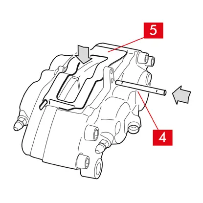
3. 캘리퍼와 패드의 전용 시트에 스프링(포인트 5)과 핀(포인트 4)을 다시 삽입합니다. 핀은 해머와 핀 드라이버를 사용하여 끝까지 박아야 합니다.
스프링을 장착할 때 방향에 유의하십시오.
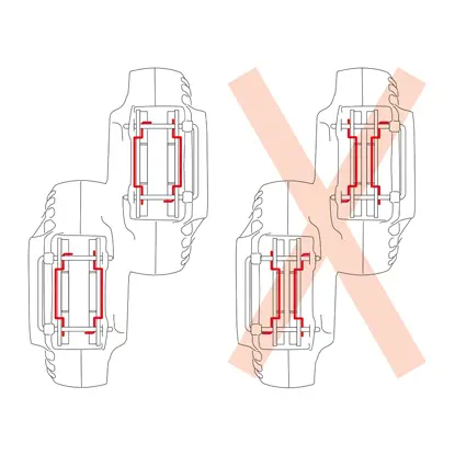
4. 스프링의 위치가 올바른지 확인합니다.
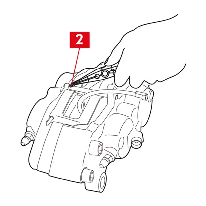
5. 안전 분할 핀(포인트 2)이 장착된 모델의 경우 플라이어를 사용하여 클립의 위치를 조정합니다.
6. 분할 핀의 위치가 올바른지 확인합니다.
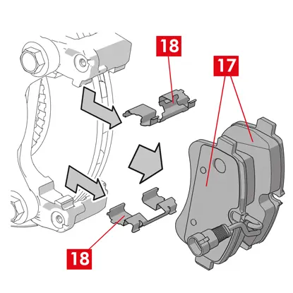
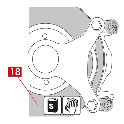
7. 탈지 제품(예: 솔벤트 SE 47)을 사용하여 디스크(포인트 18)의 제동 표면(포인트 17)을 세척합니다.
8. 새 캘리퍼를 차축에 놓고 패드 사이에 디스크(포인트 18)를 삽입합니다.
9. 개방형 스패너로 차량 제조업체에서 권장하는 조임 토크를 적용하여 고정 나사(포인트 14)를 조입니다.
또는 다음의 권장 조임 토크를 사용하십시오.
| 나사 유형 | M12x1,25 | M12x1,5 | M14x1,5 |
| 조임 토크 | 115 Nm | 125 Nm | 180 Nm |
10. 마모 표시기 케이블을 차량의 단자와 섀시 및 캘리퍼의 모든 부착물에 다시 연결합니다.
11. 브레이크 오일 공급 라인(포인트 13)을 다시 연결합니다.
12. 이전에 승객실 내부에 설치한 스페이서를 제거하여, 브레이크에서 페달을 떼고 회로가 다시 열리도록 합니다.
13. C형 후방 캘리퍼(주차 메커니즘 포함)의 경우 주차 제어 케이블(포인트 11)을 다시 연결합니다.
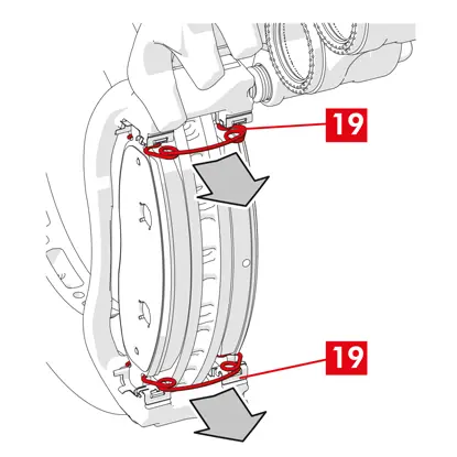
14. 레버 잠금 핀(포인트 19)을 제거합니다.
15. 차량 내부의 주차 브레이크를 밟습니다. 제동 메커니즘 레버의 스트로크가 최소값으로 다시 설정될 때까지 이 과정을 여러 번 반복합니다.
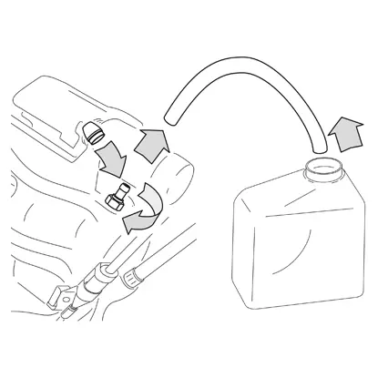
16. 브레이크 오일 저장소 캡을 엽니다.
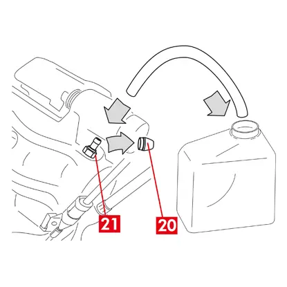
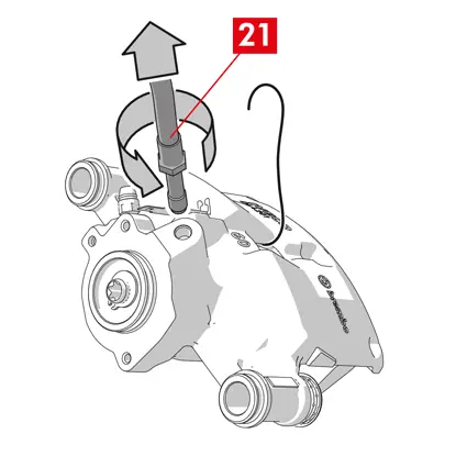
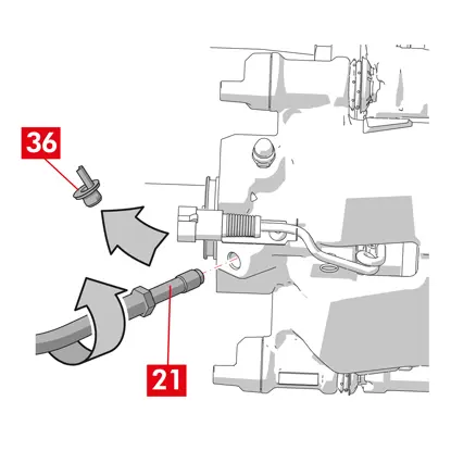
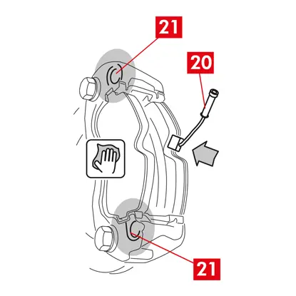
17. 보호 캡(포인트 20)을 제거하고 투명한 튜브를 캘리퍼의 블리더 플러그(포인트 21)에 연결한 다음 끝 부분을 용기에 넣어 오일을 수거합니다.
18. 블리더 플러그(포인트 21)를 엽니다.
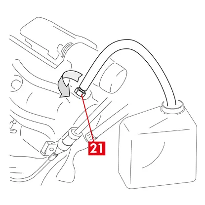
19. 블리더 플러그에서 브레이크 오일이 흘러나오기 시작할 때까지 차량 브레이크 페달을 반복해서 밟습니다.
20. 페달을 밟고 있는 상태에서 블리더 플러그를 닫습니다. 페달에서 발을 떼고 몇 초간 기다린 다음 기포가 없는 브레이크 오일이 흘러나오고 브레이크 페달의 일반적인 저항과 이동 거리가 회복될 때까지 이 과정을 반복합니다.
21. 표에 명시된 조임 토크를 적용하여 블리더 플러그를 조입니다.
| 블리더 플러그 | M6x1 | M6x1 | M6x1 | M6x1 |
| 조임 토크 | 5÷7 Nm | 7÷10 Nm | 17÷20 Nm | 18÷22 Nm |
22. 투명 튜브를 제거하고 블리더 플러그의 보호 캡을 다시 배치합니다.
23. 다른 블리더 플러그에 대해서도 블리딩 절차를 반복합니다.
24. 블리딩 과정이 끝나면 적절한 도구(예: 리트랙터)를 사용하여 캘리퍼의 피스톤을 완전히 뒤로 당긴 다음 제조업체에서 권장하는 대로 오일 잔량을 보충합니다.
25. 브레이크 오일 저장소 캡을 닫습니다.
26. 엔진이 작동하는 상태에서 차량 브레이크 페달에 강한 압력을 가하고 캘리퍼에서 오일이 새거나 회로에서 비정상적인 압력 손실이 있는지, 후방 브레이크 등이 켜지는지 확인합니다.
위험! 캘리퍼에서 오일이 새는 경우 이 문서에 설명된 모든 단계를 반복하여 원인을 정확히 파악하고 문제를 해결하십시오.
27. 주차 브레이크가 통합된 캘리퍼의 경우, 주차 브레이크 케이블 단자를 캘리퍼의 제자리에 연결합니다. 운전석 주차 브레이크를 반복해서 당겼다 놓습니다.
28. 휠을 다시 장착합니다.
29. 새 패드인 경우 런인을 수행합니다. 여분의 패드와 함께 제공된 지침을 따릅니다.
브레이크 캘리퍼 교체 지침:
중앙 스프링이 있는 플로팅 캘리퍼
이 지침의 모든 정보는 달리 명시되지 않는 한 두 가지 유형의 캘리퍼에 모두 적용됩니다.
2개 또는 4개의 사이드 스프링과 잔류 토크 감소 스프링이 있는 플로팅 캘리퍼.
교체 절차
교체를 시작하기 전에 교체에 사용되는 예비 부품이 차량 제조업체 및 모델에 적합한지 확인하십시오.
- 휠을 제거합니다.
- 올바른 재조립을 위해 부분적으로 또는 완전히 분해된 모든 구성품의 위치를 기록해 두십시오
1. 마모 표시기(포인트 1)가 있는 경우 차량의 단자에서 분리하여 캘리퍼에 고정하는 심(포인트 2)과 섀시에 있는 모든 부착물에서 분리합니다.
2. 가이드 부시에서 보호 캡(포인트 3)을 제거합니다.
3. 캡에 립(포인트 4)이 있는 경우 손가락으로 립(포인트 4)을 잡아당겨 캡을 떼어냅니다.
4. 캡이 단단한 플라스틱으로 만들어진 경우(포인트 5) 드라이버로 분리할 수 있습니다. 캡을 제거하면 파손됩니다.
경고! 분해한 단단한 플라스틱 캡은 재사용하지 마십시오.
주의! 분해할 가이드 부시는 브레이크 오일 공급 라인이 늘어나지 않고 캘리퍼 본체가 회전할 수 있는 부시를 사용해야 합니다.
경고! 가이드 부시에는 두 가지 유형이 있습니다.
- 별도의 나사 사용
- 통합된 나사 사용
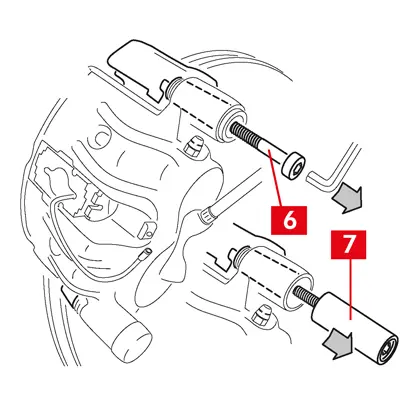
5. 스패너를 사용하여 나사(포인트 6) 또는 내장된 가이드 부시(포인트 7)를 풀고 완전히 제거합니다
경고! 캘리퍼에 브레이크 패드가 붙어 있는 경우 드라이버를 사용하여 분리하십시오.
위험! 캘리퍼 본체를 열면 잔류 토크 감소 스프링이 튀어나올 수 있습니다.
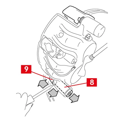
6. 가이드 부시가 통합되지 않은 경우(포인트 8), 드라이버로 캘리퍼 브래킷(포인트 9)에서 가이드 부시를 잡아당겨 제자리에서 빼냅니다.
7. 뒷바퀴의 캘리퍼를 서스펜션 및 리프 스프링으로 교체하는 경우, 캘리퍼 본체(포인트 10)를 캘리퍼 브래킷(포인트 9)에서 완전히 분리하기 위해 가이드 부시(포인트 8)를 모두 제거해야 합니다.
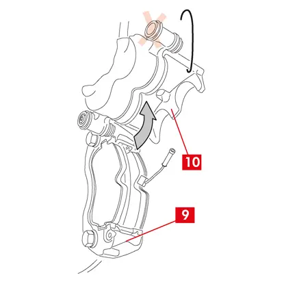
8. 캘리퍼 본체(포인트 10)를 다른 가이드 부시를 돌려서 캘리퍼 브래킷(포인트 9)에서 빼내어 패드가 캘리퍼 브래킷에서 나올 때까지 잡아당깁니다. 적절한 지지대를 사용하여 캘리퍼 본체를 차량 섀시에 부착합니다.
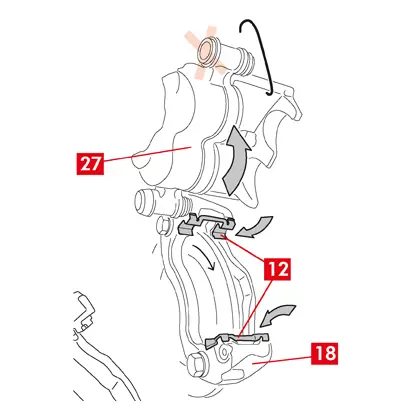
9. 새 캘리퍼에 재조립할 수 있도록 패드(포인트 11)와 스프링(포인트 12)을 손상 없이 제거합니다.
10. 패드를 잘못 재조립하지 않도록 마커를 사용하여 디스크의 회전 방향을 패드에 표시합니다.
11. 여전히 제자리에 있으면 잔류 토크 감소 스프링(13번 지점)을 제거합니다.
12. 승객실 내부의 좌석과 브레이크 페달 사이에 스페이서(포인트 14)를 배치하여 작업을 수행하는 동안 페달이 계속 눌려 있도록 합니다.
경고! 이렇게 하면 브레이크 유압 회로가 닫혀 브레이크 오일이 새는 것을 방지할 수 있습니다.
주의! 아래에 설명된 모든 단계에서 브레이크 오일이 손상될 수 있는 차량 부품, 특히 도장된 부품에 닿지 않도록 주의하십시오. 실수로 브레이크 오일이 튀거나 새면 즉시 키친타월로 닦아내고 물로 닦아내십시오.
경고! 이렇게 하면 브레이크 유압 회로가 닫혀 브레이크 오일이 새는 것을 방지할 수 있습니다.
주의! 아래에 설명된 모든 단계에서 브레이크 오일이 손상될 수 있는 차량 부품, 특히 도장된 부품에 닿지 않도록 주의하십시오. 실수로 브레이크 오일이 튀거나 새면 즉시 키친타월로 닦아내고 물로 닦아내십시오.
13. 캘리퍼의 공급 라인(포인트 15)을 손으로 완전히 풀 수 있을 정도로 느슨하게 하여 브레이크 오일이 새지 않도록 합니다.
14. 개방형 스패너를 사용하여 고정 볼트(포인트 16)를 풀고 허브 브래킷에서 캘리퍼 브래킷(포인트 9)을 제거합니다.
15. 캘리퍼 본체에서 공급 라인(포인트 15)을 분리합니다.
16. 브레이크 오일이 새는 경우 즉시 닦아냅니다.
17. 오일이 새지 않도록 공급 라인을 높게 유지합니다.
18. 주차 브레이크가 통합된 캘리퍼의 경우, 주차 브레이크 케이블을 캘리퍼의 제자리에서 분리합니다.
19. 교체할 캘리퍼를 당겨서 빼냅니다.
20. 디스크의 제동 표면(포인트 17)을 탈지 제품(예: 솔벤트 SE47)을 사용하여 청소합니다.
캘리퍼 장착 절차
주의! 공급 라인을 연결할 때까지 새 캘리퍼의 오일 주입구에서 보호 캡을 분해하지 마십시오.
새 캘리퍼를 장착하기 전에 제공된 그리스를 사용하여 부시와 더스트 커버에 윤활유를 바릅니다.
경고! EUH210 - 요청 시 안전 데이터 시트 제공.
경고! EUH208 - N-알킬화 벤조트리아졸 함유. 알레르기 반응을 유발할 수 있습니다.
1. 부시에서 보호 캡(있는 경우)을 제거합니다.
2. 통합 나사가 있는 나사 또는 가이드 부시를 풉니다.
3. 나사가 분리되어 있는 경우 나사를 완전히 빼냅니다.
4. 캘리퍼 본체를 캘리퍼 지지대에서 당겨 빼냅니다.
경고! 더스트 커버가 손상되지 않도록 커버 옆쪽의 부시를 잡아당겨 빼내십시오.
5. 커버를 제거합니다.
6. 장착할 모든 구성품, 부시 시트 및 커버 시트를 적절한 제품(예: 젖은 천)을 사용하여 깨끗이 닦습니다.
7. 허브 브래킷의 장착면을 청소합니다..
8. 새 캘리퍼 브래킷(포인트 18)을 디스크에 삽입하여 배치합니다.
9. 두 개의 고정 볼트(포인트 19 및 20)를 삽입하고 접근합니다.
10. 차량 제조업체에서 권장하는 조임 토크를 적용하여 디스크 입구 쪽(포인트 19)의 고정 볼트(전진 기어)를 조입니다.
11. 차량 제조업체에서 권장하는 조임 토크를 적용하여 두 번째 고정 볼트(포인트 20. 디스크 출구 쪽)를 조입니다.
다음의 권장 조임 토크를 참고하십시오.
| 나사 유형 | 조임 토크 |
| M12x1,25 | 115 Nm |
| M12x1,5 | 125 Nm |
| M14x1,5 | 180 Nm |
| M16x1,5 | 210 Nm |
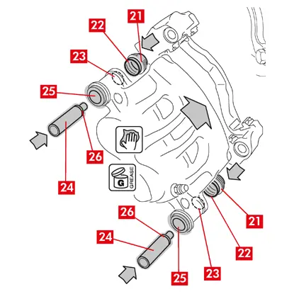
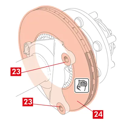
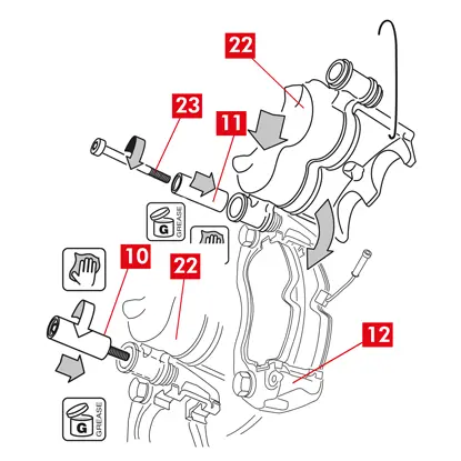
12. 커버의 전체 내부 표면(포인트 21)과 캘리퍼 본체의 접촉 프로파일(포인트 22)에 그리스를 골고루 바릅니다.
13. 커버(포인트 21)를 캘리퍼 본체의 제자리(포인트 23)에 삽입합니다.
주의! 손가락으로 커버가 캘리퍼 본체에 올바르게 삽입되고 장착되었는지 확인하십시오.
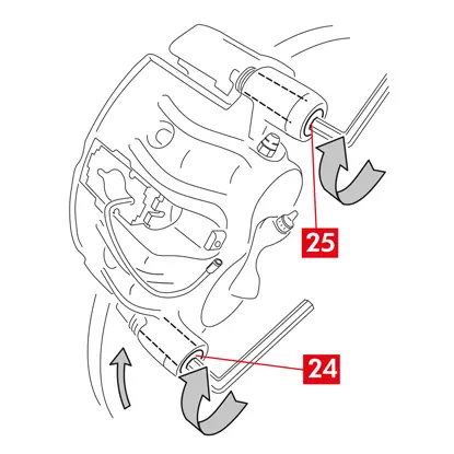
14. 캘리퍼 본체의 부시(포인트 24)와 시트(포인트 25)의 외부 표면에 그리스를 바르고 커버 반대쪽에서 캘리퍼 본체에 부시를 삽입합니다.
15. 커버(포인트 21)가 제자리(포인트 26)에 맞을 때까지 부시(포인트 24)를 밀어 넣습니다.
16. 여분의 그리스를 제거합니다.
17. 캘리퍼 본체를 캘리퍼 브래킷에 끼우고 디스크 출구 쪽(전진 기어)에 있는 나사 또는 통합된 부시를 나사로 조여 장착합니다.
18. 패드가 캘리퍼 브래킷에 들어갈 때까지 캘리퍼 본체(포인트 27)를 가이드 부시를 중심으로 비틀어 캘리퍼 브래킷(포인트 18)에서 빼냅니다. 적절한 지지대를 사용하여 캘리퍼 본체를 차량 섀시에 부착합니다.
주의! 가이드 부시 시트를 부착 지점으로 사용하지 마십시오.
패드 장착하기
1. 캘리퍼 브래킷에 측면 스프링(포인트 12)을 장착하고 적절한 압력을 가하여 단단히 부착합니다.
2. 스프링이 4개인 캘리퍼의 경우, 항상 베인이 캘리퍼 브래킷 바깥쪽을 향하도록 스프링을 장착합니다.
주의! 올바른 장착 방향을 준수하십시오.
경고! 접착면이 있는 패드가 있는 경우 새 패드를 장착해야 하며, 여분의 패드와 함께 제공된 지침을 따르십시오.
주의! 마모 표시기가 있는 패드는 분해하기 전에 원래 있던 위치에 다시 장착해야 합니다.
주의! 올바른 장착 방향을 준수하십시오.
경고! 접착면이 있는 패드가 있는 경우 새 패드를 장착해야 하며, 여분의 패드와 함께 제공된 지침을 따르십시오.
주의! 마모 표시기가 있는 패드는 분해하기 전에 원래 있던 위치에 다시 장착해야 합니다.
3. 캘리퍼 브래킷(포인트 18)에 패드(포인트 11)를 다시 삽입하고, B형 캘리퍼의 경우 드라이버를 사용하여 측면 스프링(포인트 12)을 들어올립니다.
경고! 패드에 찍힌 화살표가 디스크 회전 방향을 가리키고 있어야 합니다.
위험! 패드는 마찰 소재가 디스크를 향하도록 삽입해야 합니다.
경고! 패드에 찍힌 화살표가 디스크 회전 방향을 가리키고 있어야 합니다.
위험! 패드는 마찰 소재가 디스크를 향하도록 삽입해야 합니다.
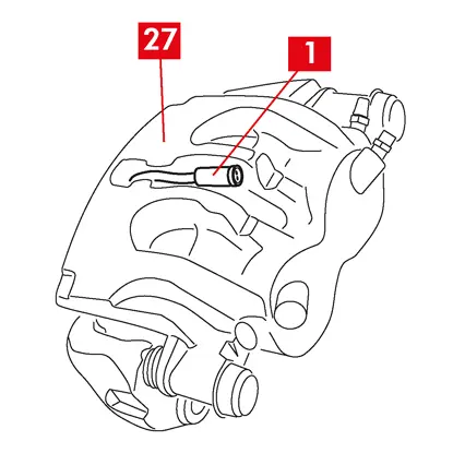
4. 마모 표시 케이블(포인트 1)을 다음과 같이 전용 덕트에 끼워 넣습니다.
A형 캘리퍼의 경우 - 스프링(포인트 28).
B형 캘리퍼의 경우 - 캘리퍼 본체(포인트 27).
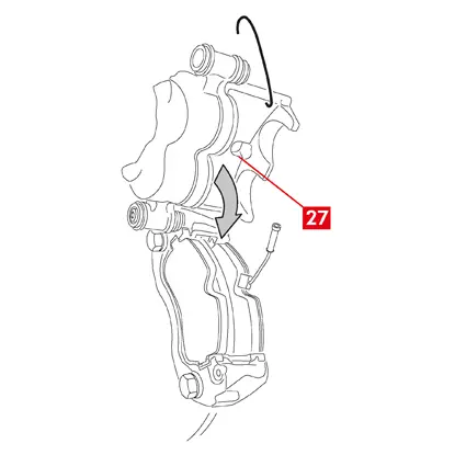
4. 나사로 조인 가이드 부시를 중심으로 캘리퍼 본체(포인트 27)를 돌려서 캘리퍼를 조심스럽게 닫습니다. 접착면이 있는 패드가 있는 경우 캘리퍼 본체 장착을 완료하기 전에 캘리퍼 본체와 패드 사이에 접촉이 발생하지 않도록 주의하십시오.
주의! 캘리퍼를 조심스럽게 닫고, 캘리퍼 브래킷에 부딪혀 부시의 보호 커버가 손상되지 않았는지 확인하십시오.
주의! 캘리퍼를 조심스럽게 닫고, 캘리퍼 브래킷에 부딪혀 부시의 보호 커버가 손상되지 않았는지 확인하십시오.
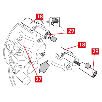
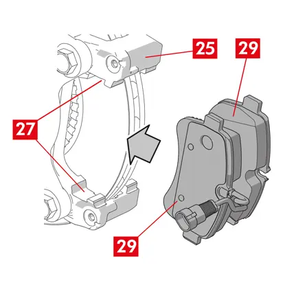
5. 캘리퍼 본체(포인트 27)를 캘리퍼 브래킷(포인트 18) 쪽으로 이동합니다.
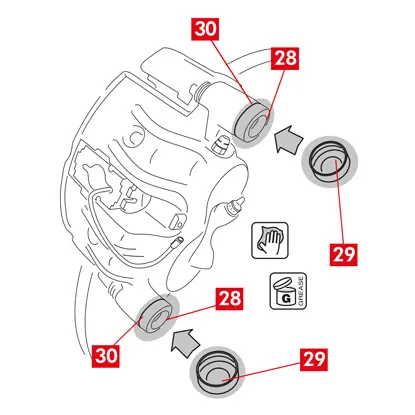
6. 가이드 부시(포인트 29)를 캘리퍼 브래킷 시트에 다시 삽입합니다.
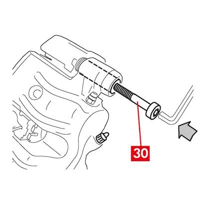
7. 새 나사(포인트 30)(있는 경우)를 삽입하고 조입니다.
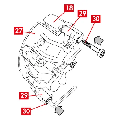
8. 서스펜션 및 리프 스프링이 있는 뒷바퀴의 캘리퍼를 교체할 때는 캘리퍼 본체(포인트 27)를 캘리퍼 브래킷(포인트 18)에 다시 배치한 다음 양쪽 가이드 부시(포인트 29)를 다시 삽입하고 새 나사 2개(포인트 30)(있는 경우)를 삽입한 후 조여야 합니다.
9. 아직 조이지 않은 경우, 가이드 부시 고정 나사 또는 통합된 가이드 부시를 디스크 진입 쪽(전진 기어)에 조입니다. 그런 다음 다른 나사 또는 다른 통합된 가이드 부시를 동일한 토크로 조입니다.
10. 다음 표에 명시된 조임 토크로 조입니다.
| 유형 | 조임 토크 | |
| 고정 나사 | (M8 – CH6) | 32 ÷ 36 Nm |
| 나사가 통합된 가이드 부시 | (M8 – CH6) | 32 ÷ 36 Nm |
| 나사가 통합된 가이드 부시 | (M10 – CH8) | 65 ÷ 75 Nm |
위험! 설명된 조임 순서를 준수하지 않으면 캘리퍼의 올바른 기능이 손상될 수 있습니다.
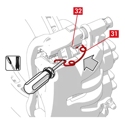
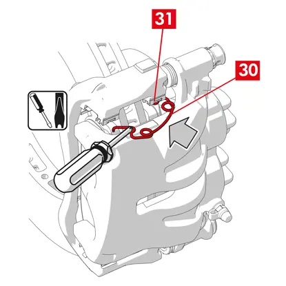
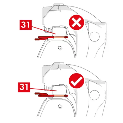
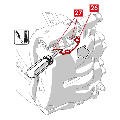
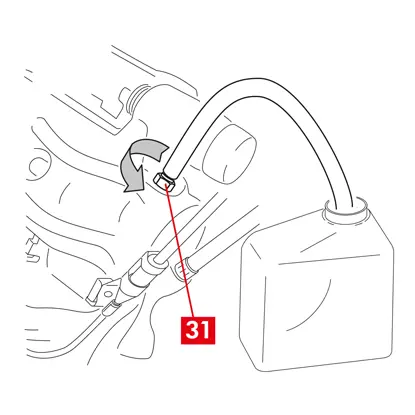
11. 잔류 토크 감소 스프링(포인트 31)의 경우 패드의 플레이트(포인트 32) 아래에 스프링을 걸고 중공 드라이버를 사용하여 다른 패드에 플레이트 밑면을 걸 수 있습니다.
위험! 스프링을 잘못 부착하면 스프링이 튀어나올 수 있습니다.
주의! 올바른 장착 방향을 준수하십시오.
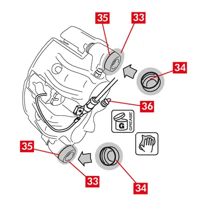
12. 부품(포인트 33)을 조심스럽게 청소하여 제자리에 잘 고정되도록 하고 새 보호 캡(포인트 34)을 장착한 후 내부 표면과 캘리퍼 본체 시트에 예비 부품 키트에 포함된 그리스를 바릅니다.
13. 보호 캡(포인트 34)을 돌려서 시트(포인트 35)에 완전히 밀착되도록 합니다.
14. 마모 표시기가 있는 경우 차량의 단자에 다시 연결하여 캘리퍼에 있는 심에 가볍게 눌러 고정하고 섀시에 있는 모든 부착물을 고정합니다.
15. 브레이크 오일 주입구(포인트 36)에서 보호 캡을 제거합니다.
16. 브레이크 오일 공급 라인을 다시 연결합니다.
17. 이전에 승객실 내부에 설치한 스페이서를 제거하여, 브레이크에서 페달을 떼고 유압 회로가 다시 열리도록 합니다.
18. 브레이크 오일 저장소 캡을 엽니다.
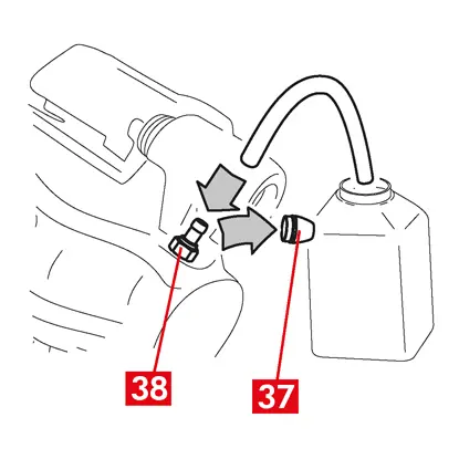
19. 보호 캡(포인트 37)을 제거하고 투명한 튜브를 캘리퍼의 블리더 플러그(포인트 38)에 연결한 다음 끝 부분을 용기에 넣어 오일을 수거합니다.
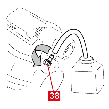
20. 블리더 플러그(포인트 38)를 엽니다.
21. 블리더 플러그에서 브레이크 오일이 흘러나오기 시작할 때까지 차량 브레이크 페달을 반복해서 밟습니다.
22. 페달을 밟고 있는 상태에서 블리더 플러그를 닫습니다. 페달에서 발을 떼고 몇 초간 기다린 다음 기포가 없는 브레이크 오일이 흘러나오고 브레이크 페달의 일반적인 저항과 이동 거리가 회복될 때까지 이 과정을 반복합니다.
23. 표에 명시된 조임 토크를 적용하여 블리더 플러그를 조입니다.
| 블리더 플러그 | M6x1 | M8x1,25 | M10x1 | M12x1 |
| 조임 토크 | 5÷7 Nm | 7÷10 Nm | 17÷20 Nm | 18÷22 Nm |
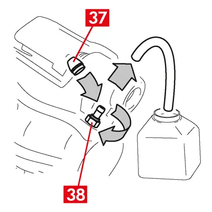
24. 투명 튜브를 제거하고 블리더 플러그의 보호 캡을 다시 배치합니다.
25. 다른 블리더 플러그에 대해서도 블리딩 절차를 반복합니다.
26. 블리딩 과정이 끝나면 적절한 도구(예: 리트랙터)를 사용하여 캘리퍼의 피스톤을 완전히 뒤로 당긴 다음 제조업체에서 권장하는 대로 오일 잔량을 보충합니다.
27. 브레이크 오일 저장소 캡을 닫습니다.
28. 엔진이 작동하는 상태에서 차량 브레이크 페달에 강한 압력을 가하고 캘리퍼에서 오일이 새거나 회로에서 비정상적인 압력 손실이 있는지, 후방 브레이크 등이 켜지는지 확인합니다.
위험! 캘리퍼에서 오일이 새는 경우 이 문서에 설명된 모든 단계를 반복하여 원인을 정확히 파악하고 문제를 해결하십시오.
29. 주차 브레이크가 통합된 캘리퍼의 경우, 주차 브레이크 케이블 단자를 캘리퍼의 제자리에 연결합니다.
30. 운전석 주차 브레이크를 반복해서 당겼다 놓습니다.
31. 휠을 다시 장착합니다.
32. 새 패드인 경우 런인을 수행합니다. 여분의 패드와 함께 제공된 지침을 따릅니다.
전동 주차 메커니즘이 통합된 상용차 플로팅 캘리퍼(유형 ECS53 및 ECS60)의 부품 교체에 대한 지침은 다음과 같습니다:
1. 액추에이터 유닛
2. 패드
3. 캘리퍼 본체(패드 및 캘리퍼 브래킷 제외)
4. 캘리퍼 브래킷
2. 패드
3. 캘리퍼 본체(패드 및 캘리퍼 브래킷 제외)
4. 캘리퍼 브래킷
경고! 팩에 포함된 예비 부품을 교체하기 전에 이 문서를 읽어보십시오. 팩에 포함된 예비 부품을 교체하는 데 필요한 단계만 수행하십시오.
교체 절차
교체를 시작하기 전에 교체에 사용되는 예비 부품이 차량 제조업체 및 모델에 적합한지 확인하십시오.
경고! 전기 고장이 발생한 경우 액추에이터 유닛을 분해하고 피스톤을 뒤로 당겨서 적절한 스패너로 Torx 나사를 시계 방향으로 돌리십시오.
- 올바른 재조립을 위해 부분적으로 또는 완전히 분해된 모든 구성품의 위치를 기록해 두십시오.
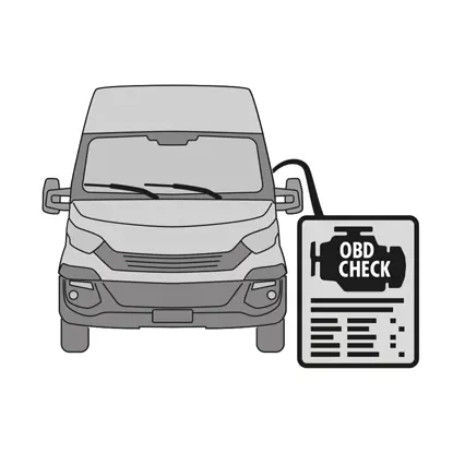
1. 진단 도구(온보드 진단 - OBD)를 차량에 연결하고 차량 제조업체에서 설명한 대로 유지보수 모드 절차에 들어갑니다.
주의! 예비 부품이 차량 소프트웨어와 호환되는지 확인하십시오.
2. 휠을 제거합니다.

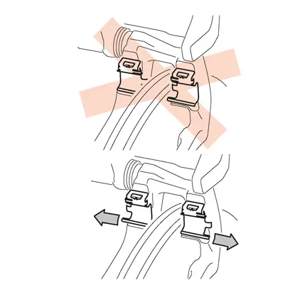
3. 케이블 글랜드에서 액추에이터 유닛의 전원 공급 케이블을 분리합니다.
4. 캘리퍼 유형 ECS60의 경우 케이블 글랜드(포인트 5)를 풀고 제거합니다.
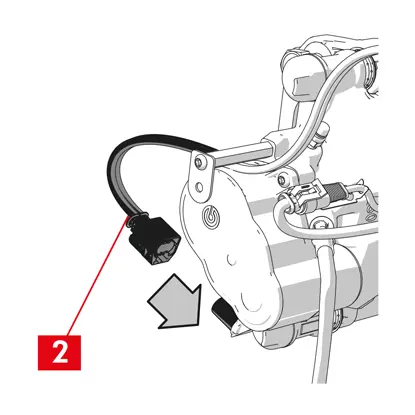
5. 액추에이터 장치에서 전기 공급 케이블(포인트 6)을 분리합니다.
경고! 커넥터에는 안전 래치가 장착되어 있을 수 있습니다.
경고! 커넥터에는 안전 래치가 장착되어 있을 수 있습니다.
액추에이터 유닛 분해하기
경고! 별도의 예비 부품이 있는 경우에만 액추에이터 유닛 분해를 진행하십시오.
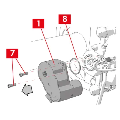
1. 액추에이터 유닛(포인트 1)에서 고정 나사(포인트 7)를 풉니다.
2. 액추에이터 유닛(포인트 1)을 제거합니다.
3. 씰(포인트 8)을 제거합니다.
패드 분해하기
주의! 재사용하려는 구성 요소를 손상시키지 마십시오.
위험! 브레이크 오일 공급 라인이 늘어나지 않도록 주의하십시오.
위험! 브레이크 오일 공급 라인이 늘어나지 않도록 주의하십시오.
1. 마모 표시기(포인트 9)가 있는 경우 차량의 단자에서 분리하여 캘리퍼에 고정하는 심과 섀시에 있는 모든 부착물에서 분리합니다.
2. 보조 부시(전진 드라이브 회전 디스크 출구 쪽)에서 보호 캡(포인트 10)을 제거합니다.
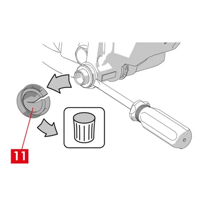
3. 캡이 단단한 플라스틱으로 만들어진 경우(포인트 11) 드라이버로 분리할 수 있습니다. 캡을 제거하면 파손됩니다.
경고! 분해한 단단한 플라스틱 캡은 재사용하지 마십시오.
4. 보조 나사(포인트 12)를 풀고 제거합니다.
5. 캘리퍼 유형 ECS60의 경우 드라이버를 사용하여 부시를 홈에서 밀어내어 캘리퍼 브래킷에서 분리합니다.
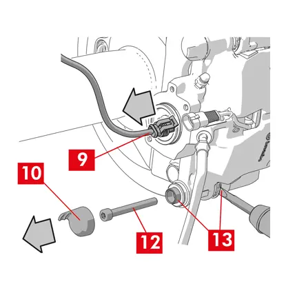
6. 기본 부시(전진 드라이브 회전 디스크 입구 쪽)에서 보호 캡(포인트 14)을 제거합니다.
7. 기본 나사(포인트 15)를 완전히 풀고 제거합니다.
경고! 드라이버를 사용하여 가이드 부시를 홈에서 들어올리십시오.
8. 기본 가이드 부시(16번 지점)를 캘리퍼 브래킷에서 분리할 수 있을 정도로 빼냅니다.
9. 브레이크 오일 공급 라인이 늘어나지 않도록 주의하면서 캘리퍼 본체(3번 지점)를 캘리퍼 브래킷(4번 지점)에서 당겨 빼냅니다.
10. 적절한 지지대를 사용하여 캘리퍼 본체를 차량 섀시에 부착합니다.
주의! 부시 시트를 부착 지점으로 사용하지 마십시오
11. 새 캘리퍼에 재조립할 수 있도록 패드(포인트 17)와 스프링(포인트 18)을 손상 없이 제거합니다.
12. 여전히 제자리에 있으면 잔류 토크 감소 스프링(19번 지점)을 제거합니다.
경고! 동일한 패드를 올바르게 다시 장착하려면 디스크의 회전 방향을 표시하는 마커로 패드에 화살표(없는 경우)를 표시하십시오.
캘리퍼 본체 분해하기
1. 승객실 내부의 좌석과 브레이크 페달 사이에 스페이서(포인트 20)를 배치하여 작업을 수행하는 동안 페달이 계속 눌려 있도록 합니다.
경고! 이렇게 하면 브레이크 유압 회로가 닫혀 브레이크 오일이 새는 것을 방지할 수 있습니다.
주의! 아래에 설명된 모든 단계에서 브레이크 오일이 손상될 수 있는 차량 부품, 특히 도장된 부품에 닿지 않도록 주의하십시오. 실수로 브레이크 오일이 튀거나 새면 즉시 키친타월로 닦아내고 물로 닦아내십시오.
2. 캘리퍼의 공급 라인(포인트 21)을 손으로 완전히 풀 수 있을 정도로 느슨하게 하여 브레이크 오일이 새지 않도록 합니다.
3. 캘리퍼 본체에서 공급 라인(포인트 21)을 분리합니다.
4. 브레이크 오일이 새는 경우 즉시 닦아냅니다.
5. 오일이 새지 않도록 공급 라인을 높게 유지합니다.
6. 캘리퍼 본체(포인트 3)를 당겨 빼냅니다.
캘리퍼 브래킷 분해하기
주의! 분해하는 동안 캘리퍼 브래킷이 실수로 떨어지지 않도록 제자리에 보관하십시오.
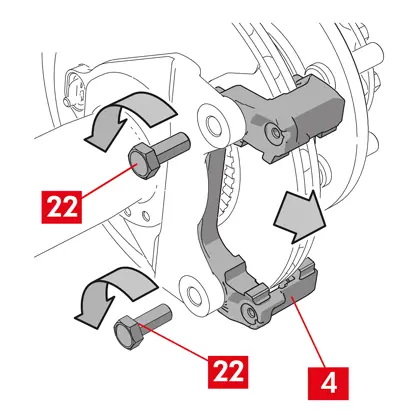
1. 고정 나사(포인트 22)를 풉니다.
2. 허브 브래킷에서 캘리퍼 브래킷(포인트 4)을 제거합니다.
장착 절차
새 예비 부품을 다시 조립합니다.
1. 장착할 모든 구성품(새 것이든 이전에 제거한 것이든), 부시 시트 및 스프링 시트를 적절한 제품(예: 젖은 천)을 사용하여 깨끗이 닦습니다.
위험! 구성품이 손상되지 않았는지 확인하고 손상된 경우 새 구성품으로 교체하십시오.
2. 허브 브래킷의 장착면(포인트 23)을 청소합니다..
3. 디스크의 제동 표면(포인트 24)을 탈지 제품(예: 솔벤트 SE47)을 사용하여 청소합니다.
캘리퍼 브래킷 장착하기
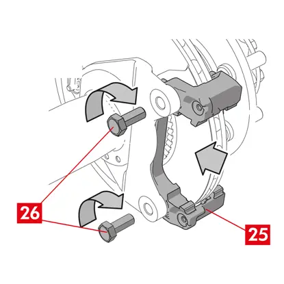
1. 새 캘리퍼 브래킷(포인트 25)을 허브 브래킷에 배치합니다.
2. 고정 나사(포인트 26)를 삽입하고 차량 제조업체에서 권장하는 조임 토크로 조입니다.
패드 및 캘리퍼 본체 장착하기
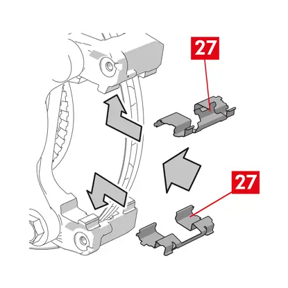
1. 스프링(포인트 27)을 다시 삽입하고 제자리에 올바른 방향으로 배치합니다.
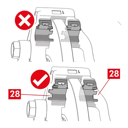
2. 스프링이 4개인 캘리퍼 유형 ECS52의 경우, 항상 베인(포인트 28)이 캘리퍼 브래킷 바깥쪽을 향하도록 스프링을 장착합니다.
경고! 접착면이 있는 패드가 있는 경우 새 패드를 장착해야 하며, 여분의 패드와 함께 제공된 지침을 따르십시오.
주의! 마모 표시기가 있는 패드는 분해하기 전에 원래 있던 위치에 다시 장착해야 합니다.
위험! 패드는 마찰 소재가 디스크를 향하도록 삽입해야 합니다.
3. 캘리퍼 브래킷(포인트 25)에 패드(포인트 29)를 다시 삽입하고 드라이버를 사용하여 측면 스프링(포인트 27)을 들어올립니다.
4. 잔류 토크 감소 스프링(포인트 30)의 경우 패드의 플레이트(포인트 31) 아래에 스프링을 걸고 중공 드라이버를 사용하여 다른 패드에 플레이트 밑면을 걸 수 있습니다.
위험! 스프링을 잘못 부착하면 스프링이 튀어나올 수 있습니다.
위험! 스프링을 잘못 부착하면 스프링이 튀어나올 수 있습니다.
주의! 올바른 장착 방향을 준수하십시오.
주의! 캘리퍼 본체가 새것인 경우, 공급 라인을 연결할 때까지 새 캘리퍼의 오일 주입구에서 보호 캡을 분해하지 마십시오.
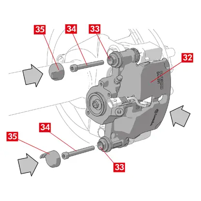
6. 캘리퍼 본체(포인트 32)를 디스크에 삽입하여 가이드 부시가 캘리퍼 브래킷의 구멍과 일치하도록 배치합니다.
주의! 커버를 손상시키지 마십시오.
7. 가이드 부시(포인트 33)를 캘리퍼 브래킷의 제자리로 밀어 넣습니다.
8. 32 ÷ 36 Nm의 조임 토크를 사용하여 나사(포인트 34)를 삽입하고 조입니다.
9. 캡(포인트 35)을 배치합니다.
주의! 보호 캡을 제거하기 전에 공급 지점을 최대한 높게 유지하여 캘리퍼 내부의 브레이크액이 새지 않도록 하십시오.
10. 마모 표시기 케이블이 있는 경우 차량의 단자에 다시 연결하여 캘리퍼의 심(있는 경우)에 가볍게 눌러 고정하고 섀시에 있는 모든 부착물을 고정합니다.
브레이크 오일 공급 라인 연결하기
1. 브레이크 오일 주입구에서 보호 캡(포인트 36)을 제거합니다.
2. 브레이크 오일 공급 라인(포인트 21)을 다시 연결합니다.
3. 이전에 승객실 내부에 설치한 스페이서를 제거하여, 브레이크에서 페달을 떼고 회로가 다시 열리도록 합니다.
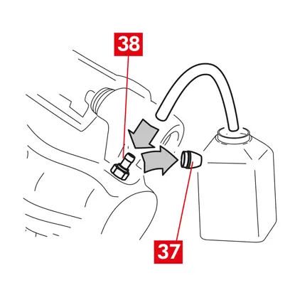
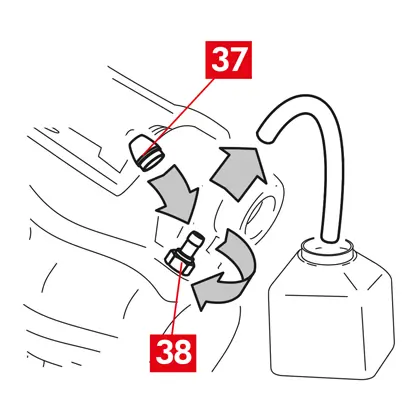
4. 블리더 플러그(포인트 38)에서 보호 캡(포인트 37)을 제거합니다.
5. 투명한 튜브를 캘리퍼의 블리더 플러그(포인트 38)에 연결한 다음 끝 부분을 용기에 넣어 오일을 수거합니다.
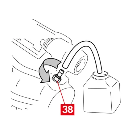
6. 블리더 플러그(포인트 38)를 엽니다.
7. 블리더 플러그에서 브레이크 오일이 흘러나오기 시작할 때까지 차량 브레이크 페달을 반복해서 밟습니다.
8. 페달을 밟고 있는 상태에서 블리더 플러그를 닫습니다. 페달에서 발을 떼고 몇 초간 기다린 다음 기포가 없는 브레이크 오일이 흘러나오고 브레이크 페달의 일반적인 저항과 이동 거리가 회복될 때까지 이 과정을 반복합니다.
9. 다음 표에 명시된 조임 토크를 적용하여 블리더 플러그(포인트 38)를 조입니다.
| 블리더 유형 | M10x1 |
| 조임 토크 | 12÷16 Nm |
10. 투명 튜브를 제거합니다.
11. 다른 블리더 플러그에 대해서도 블리딩 절차를 반복합니다.
12. 보호 캡(포인트 37)을 다시 배치합니다.
13. 블리딩 과정이 끝나면 적절한 도구(예: 리트랙터)를 사용하여 캘리퍼의 피스톤을 완전히 뒤로 당긴 다음 제조업체에서 권장하는 대로 오일 잔량을 보충합니다.
14. 엔진이 작동하는 상태에서 차량 브레이크 페달에 강한 압력을 가하고 캘리퍼에서 오일이 새거나 회로에서 비정상적인 압력 손실이 있는지, 후방 브레이크 등이 켜지는지 확인합니다.
위험! 캘리퍼에서 오일이 새는 경우 이 문서에 설명된 모든 단계를 반복하여 원인을 정확히 파악하고 문제를 해결하십시오.
액추에이터 유닛 장착하기
경고! 액추에이터 유닛은 캘리퍼 본체에 이미 장착된 상태로 제공될 수 있습니다.
새 예비 부품을 다시 조립합니다.
- 다시 조립하기 전에 이전에 제거한 구성 요소를 청소합니다.
주의! 항상 나사 잠금 장치가 있는 새 나사를 사용하십시오. 항상 새 씰을 장착하십시오
위험! 구성품이 손상되지 않았는지 확인하고 손상된 경우 새 구성품으로 교체하십시오
1. 캘리퍼와 액추에이터 유닛의 접촉면을 청소합니다.
2. 나사산 나사 시트에서 나사 락커 잔여물을 제거합니다.
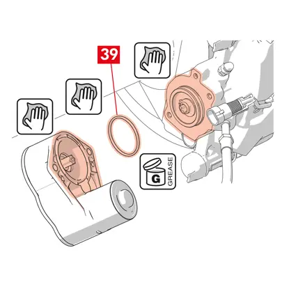
3. 씰(포인트 39)을 청소하고 제공된 그리스로 윤활합니다.
4. 액추에이터 유닛 커플링의 내경을 제공된 그리스로 윤활합니다.
경고! EUH210 - 요청 시 안전 데이터 시트 제공.
경고! EUH208 - N-알킬화 벤조트리아졸 함유. 알레르기 반응을 유발할 수 있습니다.

5. 씰(포인트 39)을 캘리퍼 본체의 제자리(포인트 40)에 배치합니다.
6. 액추에이터 유닛(포인트 41)을 캘리퍼 본체의 Torx 나사(포인트 42)에 장착합니다.
7. 액추에이터 유닛(포인트 41)을 돌려 고정 나사(포인트 44)의 구멍(포인트 43)이 원래의 장착 위치와 일치하도록 합니다.
주의! 캘리퍼 본체에 액추에이터 유닛을 장착할 때 씰(포인트 39)이 끼이지 않도록 주의하십시오.
8. 고정 나사(포인트 44)를 삽입하고 7 ÷ 10 Nm의 조임 토크로 조입니다.
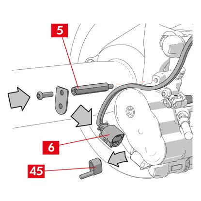
9. 보호 캡(포인트 45)(있는 경우)을 제거하고 전기 공급 케이블(포인트 6)을 연결합니다.
10. 이전에 제거한 경우 케이블 글랜드(포인트 5)를 나사로 고정합니다.
11. 액추에이터 유닛의 전원 공급 케이블을 케이블 글랜드(포인트 5)에 고정합니다.
최종 단계
1. 휠을 다시 장착합니다.
2. 재설정 절차(조립 확인)를 수행합니다.
3. 필요한 경우 차량 제조업체의 지침에 따라 카운터를 재설정(내부 카운터 재설정)합니다.
4. 차량 제조업체에서 요구하는 경우 패드를 런인합니다.
5. 진단 장치를 분리합니다. (온보드 진단 – OBD).
2개 또는 4개의 사이드 스프링과 잔류 토크 감소 스프링이 있는 플로팅 캘리퍼용 캘리퍼 본체 교체에 대한 지침은 다음과 같습니다.
고정 나사만 교체할 때는 관련 부분만 참조하십시오.
교체 절차
교체를 시작하기 전에 교체에 사용되는 예비 부품이 차량 제조업체 및 모델에 적합한지 확인하십시오.
- 올바른 재조립을 위해 부분적으로 또는 완전히 분해된 모든 구성품의 위치를 기록해 두십시오.
- 휠을 제거합니다.
ECS 캘리퍼의 경우
경고! 전기 고장이 발생한 경우 액추에이터 유닛(포인트 5)을 분해하고 피스톤을 뒤로 당겨서 적절한 스패너로 Torx 나사를 시계 방향으로 돌리십시오
1. 진단 도구(온보드 진단 - OBD)를 차량에 연결하고 차량 제조업체에서 설명한 대로 유지보수 모드 절차에 들어갑니다.
주의! 이 작업을 수행하지 않으면 리트랙터 또는 다른 적절한 도구로 피스톤을 뒤로 당길 수 없습니다.
주의! 예비 부품이 차량 소프트웨어와 호환되는지 확인하십시오.
2. 액추에이터 장치에서 전기 공급 케이블(포인트 2)을 분리합니다.
경고! 커넥터에는 안전 래치가 장착되어 있을 수 있습니다.
모든 유형의 캘리퍼
1. 주차 브레이크가 있는 캘리퍼의 경우 캘리퍼에서 제어 케이블(포인트 3)을 분리합니다.
2. 마모 표시기(포인트 4)가 있는 경우 차량의 단자에서 분리하여 캘리퍼에 고정하는 심(포인트 5)과 섀시에 있는 모든 부착물에서 분리합니다.

3. 가이드 부시에서 보호 캡(포인트 6)을 제거합니다.
4. 캡에 립(포인트 7)이 있는 경우 손가락으로 립(포인트 7)을 잡아당겨 캡을 떼어냅니다.

5. 캡이 단단한 플라스틱으로 만들어진 경우(포인트 8) 드라이버로 분리할 수 있습니다. 캡을 제거하면 파손됩니다.
경고! 분해한 단단한 플라스틱 캡은 재사용하지 마십시오.
주의! 분해할 가이드 부시는 브레이크 오일 공급 라인이 늘어나지 않고 캘리퍼 본체가 회전할 수 있는 부시를 사용해야 합니다.
경고! 가이드 부시에는 두 가지 유형이 있습니다: 별도의 나사 사용, 통합된 나사 사용.
경고! 분해한 단단한 플라스틱 캡은 재사용하지 마십시오.
주의! 분해할 가이드 부시는 브레이크 오일 공급 라인이 늘어나지 않고 캘리퍼 본체가 회전할 수 있는 부시를 사용해야 합니다.
경고! 가이드 부시에는 두 가지 유형이 있습니다: 별도의 나사 사용, 통합된 나사 사용.
6. 스패너를 사용하여 나사(포인트 9) 또는 내장된 가이드 부시(포인트 10)를 풀고 완전히 제거합니다.
7. 가이드 부시가 통합되지 않은 경우(포인트 11), 드라이버로 캘리퍼 브래킷(포인트 12)에서 가이드 부시를 잡아당겨 제자리에서 빼냅니다.
8. 뒷바퀴의 캘리퍼를 서스펜션 및 리프 스프링으로 교체하는 경우, 캘리퍼 본체(포인트 13)를 캘리퍼 브래킷(포인트 12)에서 완전히 분리하기 위해 가이드 부시(포인트 11)를 모두 제거해야 합니다.
경고! 캘리퍼에 접착된 브레이크 패드가 있는 경우 드라이버를 사용하여 분리하고 캘리퍼의 고무 부분이 손상되지 않도록 주의하십시오.
위험! 캘리퍼 본체를 열면 잔류 토크 감소 스프링이 튀어나올 수 있습니다.
9. 캘리퍼 본체(포인트 13)를 다른 가이드 부시를 돌려서 캘리퍼 브래킷(포인트 12)에서 빼내어 패드(포인트 14)가 캘리퍼 브래킷에서 나올 때까지 잡아당깁니다. 적절한 지지대를 사용하여 캘리퍼 본체를 차량 섀시에 부착합니다. 부시 시트를 부착 지점으로 사용하지 마십시오.
11. 패드(포인트 14번 지점)가 손상되지 않도록 주의하여 제거합니다.
12. 패드를 잘못 재조립하지 않도록 마커를 사용하여 디스크의 회전 방향을 패드에 표시합니다.
14. 여전히 제자리에 있으면 잔류 토크 감소 스프링(15번 지점)을 제거합니다.
15. 승객실 내부의 좌석과 브레이크 페달 사이에 스페이서(포인트 16)를 배치하여 작업을 수행하는 동안 페달이 계속 눌려 있도록 합니다.
경고! 이렇게 하면 브레이크 유압 회로가 닫혀 브레이크 오일이 새는 것을 방지할 수 있습니다.
주의! 아래에 설명된 모든 단계에서 브레이크 오일이 손상될 수 있는 차량 부품, 특히 도장된 부품에 닿지 않도록 주의하십시오. 실수로 브레이크 오일이 튀거나 새면 즉시 키친타월로 닦아내고 물로 닦아내십시오.
주의! 아래에 설명된 모든 단계에서 브레이크 오일이 손상될 수 있는 차량 부품, 특히 도장된 부품에 닿지 않도록 주의하십시오. 실수로 브레이크 오일이 튀거나 새면 즉시 키친타월로 닦아내고 물로 닦아내십시오.
16. 캘리퍼의 공급 라인(포인트 17)을 손으로 완전히 풀 수 있을 정도로 느슨하게 하여 브레이크 오일이 새지 않도록 합니다.
17. 나사(포인트 9) 또는 통합된 가이드 부시(포인트 10)를 완전히 풀고 제거합니다.
18. 가이드 부시가 통합되지 않은 경우(포인트 11), 드라이버로 캘리퍼 브래킷(포인트 12)에서 가이드 부시를 잡아당겨 제자리에서 빼냅니다.
19. 브레이크 오일 공급 라인이 늘어나지 않도록 주의하면서 캘리퍼 본체(13번 지점)를 캘리퍼 브래킷(12번 지점)에서 당겨 빼냅니다.
20. 캘리퍼 본체에서 공급 라인(포인트 17)을 분리합니다.
21. 브레이크 오일이 새는 경우 즉시 닦아냅니다.
22. 브레이크 오일이 새지 않도록 공급 라인을 높게 유지합니다.
23. 교체할 캘리퍼를 당겨서 빼냅니다.
24. 주차 브레이크가 통합된 캘리퍼의 경우, 주차 브레이크 케이블을 캘리퍼의 제자리에서 분리합니다.
25. 디스크의 제동 표면을 탈지 제품(예: 솔벤트 SE47)을 사용하여 청소합니다.
패드 장착하기
주의! 접착면이 있는 패드가 있는 경우 새 패드를 장착해야 하며, 여분의 패드와 함께 제공된 지침을 따르십시오.
1.스프링의 위치가 올바른지 확인합니다. 스프링이 4개인 캘리퍼의 경우, 베인이 항상 캘리퍼 브래킷 바깥쪽을 향하도록 합니다.
주의! 스프링 위치가 잘못되면 부상을 입을 수 있습니다.
2. 캘리퍼 브래킷(포인트 12)에 패드(포인트 14)를 삽입합니다. 드라이버를 사용하여 측면 스프링을 누릅니다.
경고! 패드에 찍힌 화살표가 디스크 회전 방향을 가리키고 있어야 합니다.
위험! 패드는 마찰 소재가 디스크를 향하도록 삽입해야 합니다.
주의! 마모 표시기가 있는 패드는 분해하기 전에 원래 있던 위치에 다시 장착해야 합니다.
경고! 패드에 찍힌 화살표가 디스크 회전 방향을 가리키고 있어야 합니다.
위험! 패드는 마찰 소재가 디스크를 향하도록 삽입해야 합니다.
주의! 마모 표시기가 있는 패드는 분해하기 전에 원래 있던 위치에 다시 장착해야 합니다.
3. 마모 표시 단자(포인트 20)가 있는 경우 피스톤 반대편 패드에 부착하고 필요한 경우 교체합니다.
주의! 마모 표시 단자를 부착할 때 가장 튀어나온 부분이 패드의 마찰면을 향하도록 하십시오.
주의! 마모 표시 단자를 부착할 때 가장 튀어나온 부분이 패드의 마찰면을 향하도록 하십시오.
캘리퍼 본체 장착하기
주의! 주차 브레이크가 장착된 캘리퍼의 경우 - 캘리퍼 본체가 브레이크 디스크에서 분리되어 있거나 브레이크 패드가 없는 상태에서는 스프링이 손상되거나 브레이크 오일이 누출될 수 있으므로 유압으로 또는 레버를 사용하여 피스톤을 움직이지 마십시오.
1. 캘리퍼 브래킷에서 캘리퍼 본체(가이드 시트)가 있는 장착 부분(포인트 21)을 젖은 천으로 닦습니다.
주의! 니트로 테트라클로로에틸렌 시너, 휘발유 등 보호 커버를 손상시킬 수 있는 제품을 사용하지 마십시오.
2. 커버의 전체 내부 표면, 가이드 부시의 외부 표면 및 캘리퍼 본체의 시트를 청소하고 그리스를 균일하게 바릅니다.
3. 캘리퍼 브래킷(포인트 12)의 시트에 두 개의 가이드 부시(포인트 10) 중 하나를 설치하여 새 캘리퍼 본체(22번 지점)를 배치합니다.
주의! 튜브가 완전히 연결될 때까지 브레이크 오일 주입구에서 보호 캡을 제거하지 마십시오.
주의! 튜브가 완전히 연결될 때까지 브레이크 오일 주입구에서 보호 캡을 제거하지 마십시오.
4. 가이드 부시가 통합되지 않은 경우(포인트 11) 새 나사(포인트 23)를 끼우고 조입니다.
5. 캘리퍼 본체(포인트 22)를 장착된 가이드 부시 주위로 돌려서 캘리퍼를 조심스럽게 닫습니다.

주의! 캘리퍼를 조심스럽게 닫고, 캘리퍼 지지대에 부딪혀 부시의 보호 커버가 손상되지 않았는지 확인하십시오. 필요한 경우 커버를 교체하십시오.
경고! 접착면이 있는 패드가 있는 경우 캘리퍼 본체 피팅을 완료하기 전에 본체와 패드 사이에 접촉이 발생하지 않도록 주의하십시오.
6. 마모 표시 프로브(포인트 20)를 캘리퍼 본체의 전용 구멍(포인트 22)에 끼워 넣습니다.
7. 다른 가이드 부시(포인트 10)를 캘리퍼 브래킷 시트(포인트 12)에 다시 삽입합니다.
8. 가이드 부시가 통합되지 않은 경우(포인트 11) 새 나사(포인트 24)를 끼우고 조입니다.
주의! 서스펜션 및 리프 스프링이 있는 뒷바퀴의 캘리퍼 브래킷을 교체할 때는 캘리퍼 본체를 캘리퍼 브래킷에 다시 배치한 다음 양쪽 가이드 부시를 다시 삽입하고 새 나사 2개를 삽입한 후 조여야 합니다.
9. 가이드 부시 고정 나사 또는 통합된 가이드 부시(포인트 24)를 디스크 진입 쪽(전진 기어)에 조입니다. 그런 다음 다른 나사 또는 통합된 가이드 부시(포인트 25)를 동일한 토크로 조입니다.
10. 다음 표에 명시된 조임 토크로 조입니다.
| 유형 | 조임 토크 | |
| 고정 나사 | (M8 – CH6) | 32 ÷ 36 Nm |
| 나사가 통합된 가이드 부시 | (M8 – CH6) | 32 ÷ 36 Nm |
| 나사가 통합된 가이드 부시 | (M10 – CH8) | 65 ÷ 75 Nm |
위험! 설명된 조임 순서를 준수하지 않으면 캘리퍼의 올바른 기능이 손상될 수 있습니다.
11. 잔류 토크 감소 스프링(포인트 26)의 경우 패드의 플레이트(포인트 27) 아래에 스프링을 걸고 중공 드라이버를 사용하여 다른 패드에 플레이트 밑면을 걸 수 있습니다.
위험! 스프링을 잘못 부착하면 스프링이 튀어나올 수 있습니다.
주의! 올바른 장착 방향을 준수하십시오.
12. 부품(포인트 28)을 조심스럽게 청소하여 제자리에 잘 고정되도록 하고 새 보호 캡(포인트 29)을 장착한 후 내부 표면과 캘리퍼 본체 시트에 예비 부품 키트에 포함된 그리스를 바릅니다.
경고! EUH210 - 요청 시 안전 데이터 시트 제공.
경고! EUH208 - N-알킬화 벤조트리아졸 함유. 알레르기 반응을 유발할 수 있습니다.
경고! EUH208 - N-알킬화 벤조트리아졸 함유. 알레르기 반응을 유발할 수 있습니다.
13. 보호 캡(포인트 29)을 돌려서 시트(포인트 30)에 완전히 밀착되도록 합니다.
14. 마모 표시기가 있는 경우 차량의 단자에 다시 연결하여 캘리퍼에 있는 심에 가볍게 눌러 고정하고 섀시에 있는 모든 부착물을 고정합니다.
15. 브레이크 오일 주입구에서 보호 캡을 제거합니다.
16. 브레이크 오일 공급 라인을 다시 연결합니다.
17. 이전에 승객실 내부에 설치한 스페이서를 제거하여, 브레이크에서 페달을 떼고 회로가 다시 열리도록 합니다.
주차 브레이크가 장착된 캘리퍼의 경우
주의! 피스톤을 패드와 조립하기 전에 캘리퍼 브래킷, 패드 및 디스크가 있는지 확인하십시오.
- 레버를 사용하여 피스톤을 패드와 조립합니다.
주의! 유압식 작동은 피스톤이 패드에서 1mm 미만인 경우에만 허용됩니다.
모든 유형의 캘리퍼
1. 투명한 튜브를 캘리퍼의 블리더 플러그(포인트 31)에 연결한 다음 끝 부분을 용기에 넣어 오일을 수거합니다.
2. 블리더 플러그(포인트 31)를 엽니다.
3. 블리더 플러그에서 브레이크 오일이 흘러나오기 시작할 때까지 차량 브레이크 페달을 반복해서 밟습니다.
4. 페달을 밟고 있는 상태에서 블리더 플러그를 닫습니다. 페달에서 발을 떼고 몇 초간 기다린 다음 기포가 없는 브레이크 오일이 흘러나오고 브레이크 페달의 일반적인 저항과 이동 거리가 회복될 때까지 이 과정을 반복합니다.
5. 표에 명시된 조임 토크를 적용하여 블리더 플러그를 조입니다.
| 블리더 플러그 | M6x1 | M8x1,25 | M10x1 | M12x1 |
| 조임 토크 | 5÷7 Nm | 7÷10 Nm | 17÷20 Nm | 18÷22 Nm |
6. 투명 튜브를 제거하고 블리더 플러그의 보호 캡을 다시 배치합니다.
7. 다른 블리더 플러그에 대해서도 블리딩 절차를 반복합니다.
8. 블리딩 과정이 끝나면 적절한 도구(예: 리트랙터)를 사용하여 캘리퍼의 피스톤을 완전히 뒤로 당긴 다음 제조업체에서 권장하는 대로 오일 잔량을 보충합니다.
9. 브레이크 오일 저장소 캡을 닫습니다.
10. 엔진이 작동하는 상태에서 차량 브레이크 페달에 강한 압력을 가하고 캘리퍼에서 오일이 새거나 회로에서 비정상적인 압력 손실이 있는지, 후방 브레이크 등이 켜지는지 확인합니다.
위험! 캘리퍼에서 오일이 새는 경우 이 문서에 설명된 모든 단계를 반복하여 원인을 정확히 파악하고 문제를 해결하십시오.
주차 브레이크가 장착된 캘리퍼의 경우
- 마모 표시기가 있는 경우 차량의 단자에 다시 연결하여 캘리퍼에 있는 심에 가볍게 눌러 고정하고 섀시에 있는 모든 부착물을 고정합니다.
- 제어 케이블의 장력을 올바르게 복원합니다.
- 정상적인 스트로크가 회복될 때까지 차량 운전석의 주차 브레이크 레버를 반복해서 조작합니다.
ECS 캘리퍼의 경우
1. 보호 캡(있는 경우)을 제거하고 전기 공급 케이블(포인트 2)을 연결합니다.
2. 재설정 절차(조립 확인)를 수행합니다.
3. 필요한 경우 차량 제조업체의 지침에 따라 카운터를 재설정(내부 카운터 재설정)합니다.

4. 차량 제조업체에서 요구하는 경우 패드를 런인합니다.
5. 진단 장치(온보드 진단 - OBD)를 분리합니다.
모든 유형의 캘리퍼
1. 휠을 다시 장착합니다.
2. 새 패드인 경우 런인을 수행합니다. 여분의 패드와 함께 제공된 지침을 따릅니다.
2. 새 패드인 경우 런인을 수행합니다. 여분의 패드와 함께 제공된 지침을 따릅니다.
보증 제한
본 보증은 상품 배송 후 2년 이내에 발생하는 모든 적합성 결함에 적용됩니다. 소비자는 해당 결함을 발견한 날로부터 2개월 이내에 판매자에게 적합성 결함을 신고해야 하며, 결함의 구제를 위한 조치를 취할 수 있는 제한 기간이 상품 인도일로부터 26개월이라는 사실을 침해하지 않는 범위 내에서 신고해야 합니다. 적합성 결함의 경우, 사용자는 법률이 정하는 바에 따라 상품의 수리 또는 교체 또는 적절한 가격 인하 또는 계약 해지를 요구할 권리가 있습니다. 소비자법 130조에 따릅니다(해당되는 경우).
본 보증은 본 제품과 관련하여 제공되는 유일한 보증이며 구두 및 서면으로 제공되는 다른 모든 보증을 대체합니다.
결함이 발생한 경우 사용자는:
- 무효화 시 60일 이내에 제조업체 및 유통업체에 서면으로 통지해야 하며, 동시에 사용자는 제품 또는 반품된 부품에서 발견된 결함에 대한 설명과 제품 및 구매 날짜(소매 구매 또는 제품 설치의 일부로 유통업체에서 판매)가 모두 명시된 원래 사용자의 구매 증빙 자료를 제공해야 합니다.
- 결함이 있는 것으로 추정되는 제품을 유통망을 통해 이탈리아 Brembo 25-24035 Curno(BG)를 경유하여 Brembo S.p.A. 본사로 보내야 합니다.
다음과 같은 경우에는 보증이 적용되지 않습니다:
- 잘못된 사용, 사고, 화재, 화학적 부식, 예정된 목적 이외의 사용, 불법 사용, 예정된 모델과 다른 모델 사용, 잘못된 설치, 제조업체의 지침에 반하는 설치 또는 제조업체가 제공한 지침에 명시된 제품 유지보수 부족으로 인해 제품의 일부 또는 전체가 손상된 경우
- 편안함, 소음, 진동 또는 거친 승차감과 관련된 불만 사항.
본 제품은 Brembo 웹사이트(www.brembo.com)에서 제공되는 Brembo 카탈로그 및/또는 브렘보 제품 유통업체에 의해 특정 모델 및 용도에 맞게 설계 및 생산되었습니다. 본 제품은 고속도로법 규정 준수를 포함하되 이에 국한되지 않고 제품이 설치된 차량이 사용되는 주 및/또는 국가에서 시행 중인 법률에 따라 사용해야 하며, 주 및/또는 국가에서 요구하는 모든 인가/승인, 허가 또는 면허를 취득한 후에 사용해야 합니다.
유럽 연합 회원국 영토에서 판매되는 제품의 경우, 본 보증 제한은 1985년 7월 25일자 유럽 연합 이사회 지침 85/374/EEC의 규정에 따라 적용됩니다.
미국 영토에서 판매되는 제품의 경우, 본 보증 제한은 해당 연방법 또는 주법에 따라 적용됩니다.
일반 및 안전 정보
이 Brembo 제품은 모든 관련 안전 표준을 준수하도록 설계되었습니다. 제품은 설계 및 제조된 특정 용도와 다르게 사용하도록 되어 있지 않습니다. 다른 목적으로 사용하거나 제품을 변경 또는 변조하면 제품 성능에 영향을 미치고 제품이 안전하지 않게 될 수 있습니다.
이러한 변경 또는 부적절한 사용은 제한 보증을 무효화하며, 제품을 사용하는 개인이 타인의 신체적 상해 또는 재산상의 손해에 대한 책임을 져야 할 수 있습니다.
이 지침에서 "위험!” 경고는 준수하지 않을 경우 심각한 부상 또는 사망을 초래할 가능성이 높은 절차를 의미합니다. “주의!”는 준수하지 않을 경우 물리적 손상을 초래할 수 있는 절차를 의미하며, “경고!”는 준수하지 않을 경우 차량 손상을 초래할 수 있는 절차를 의미합니다
위험!
교체를 시작하기 전에 예비 부품이 차량 제조사 및 모델에 적합한지 확인하십시오. 본 제품은 설치되는 차량의 안전한 운행에 필수적이며, 본 제품의 설치 및 사용에 대한 교육을 받았거나 경험이 있는 숙련되고 자격을 갖춘 사람만 설치하도록 되어 있습니다.
설치 담당자는 적절한 도구를 갖추고 차량 수리를 처리할 수 있는 지식과 경험을 갖추고 있어야 합니다. 본 지침을 충실하고 완벽하게 따르지 않았거나 기타 이유로 인해 부적절하거나 잘못된 설치는 제한 보증을 무효화하며, 신체적 상해 또는 재산상의 손해가 발생할 경우 설치자에게 책임이 부과될 수 있습니다.
Brembo는 교체 제품이 부적절하게 설치된 차량을 운전하는 사람으로 인해 또는 그로 인해 발생한 어떠한 손상이나 상해에 대해서도 책임을 지지 않습니다.
주의!
교체된 부품은 법률에 따라 폐기해야 합니다.
제품, 부품 및 구성품을 세게 치거나 손상시키지 마십시오. 그렇게 하면 제품, 부품 및 구성품의 효율성이 저하되고 오작동을 일으킬 수 있습니다. 필요한 경우 손상된 부품이나 구성 요소를 교체하십시오. 부상을 방지하기 위해 다음을 권장합니다.
- 부품을 청소하는 동안 발생하는 먼지를 흡입하지 않도록 적절한 장비를 사용하십시오.
- 날카로운 모서리가 있는 부품을 분해하고 조립할 때는 항상 장갑을 착용하십시오.
- 피부 표면이 패드와 브레이크 슈의 마찰 물질에 직접 닿으면 찰과상을 입을 수 있으므로 주의하십시오.
- 압축 공기를 사용하여 캘리퍼 피스톤을 제거할 때 손이 눌릴 위험이 있으므로 패드 시트에 손을 넣지 마십시오.
- 브레이크액은 피부와 눈에 자극을 줄 수 있으므로 직접 닿지 않도록 주의하십시오. 실수로 접촉한 경우 차량 또는 브레이크 오일 제조업체의 지침에 따라 철저히 세척하십시오.
- 전기 부품에 정전기가 발생하거나 플라스틱 부품이 손상될 수 있는 충격이 가해지지 않도록 주의하십시오.
- 분해한 전기 부품을 습기로부터 보호하십시오.
- 전기 접점이 올바르게 연결되어 있는지 확인하고 경고등이 켜지는지 점검하십시오. 그렇지 않은 경우 경고등이 작동하지 않으면 제동 시스템의 효율성이 떨어지거나 브레이크 신호 고장이 발생할 수 있습니다.
- 그리스 및 기타 윤활유가 브레이크 디스크, 드럼, 패드 및 슈의 제동 표면에 닿으면 제동 시스템의 효율성에 영향을 미치고 심각한 물리적 손상을 초래할 수 있으므로 주의하십시오.
- 고무 부품을 장착할 때 날카로운 도구를 사용하면 손상될 수 있으니 주의하십시오. 손상된 부품이 있으면 교체하십시오.
보증 제한
보증은 제품 배송 후 2년 이내에 발생하는 적합성 결여에 적용됩니다. 결함이 발견된 경우 발견일로부터 60일 이내, 제품 구매일로부터 2년 이내에 신고해야 합니다. 결함이 확인되고 보증이 적용되는 경우, 제품을 수리하거나 새 제품 또는 완전히 리퍼브된 제품으로 교체해 드립니다. 보증은 전적으로 또는 특히 제품의 잘못된 사용, 사고, 화재, 화학적 부식 또는 잘못된 설치로 인한 결함에는 적용되지 않습니다.
어떻게 도와드릴까요?