Instructions for the replacement of the motorcycle wheel and brake disc
Conventions
The illustrations are provided as a guide. Before beginning the replacement procedure, check that the material is suitable for the make and model of vehicle.
CAUTION! To replace the brake disc, the wheel must always be removed from the vehicle.
WARNING! During all the operations described below, the caliper fluid inlet hose must NOT be disconnected.
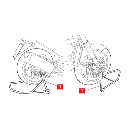
1. Position the vehicle on the stands (point 1).
WARNING! To ensure correct refitting, note the position of the components to be removed.
WARNING! To ensure correct refitting, note the position of the components to be removed.
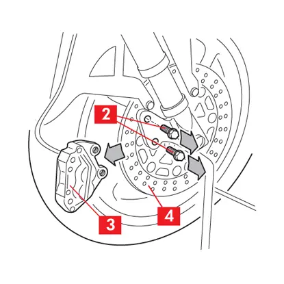
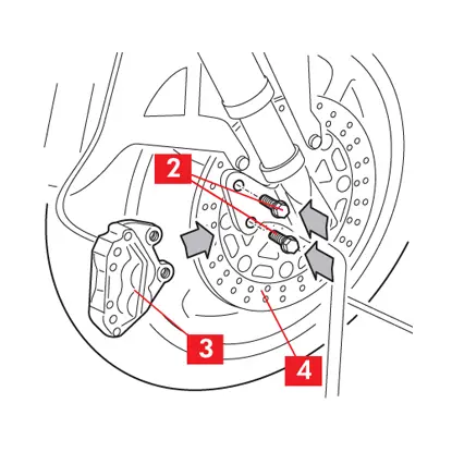
2. Loosen the fastening screws (point 2) of the caliper or calipers.
3. Move the caliper or calipers (point 3) away from the disc (point 4).
4. Hook the caliper or calipers to the vehicle chassis by means of appropriate supports.
CAUTION! Avoid kinking or tensioning the brake fluid supply pipe.
CAUTION! Avoid kinking or tensioning the brake fluid supply pipe.
5. If the pads obstruct extraction of the caliper, gently oscillate the caliper until the pistons are retracted far enough for the caliper to move away from the disc.
Removing the front wheel
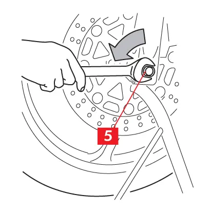
1. Unscrew the nut (point 5) on the pin.
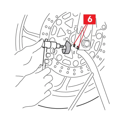
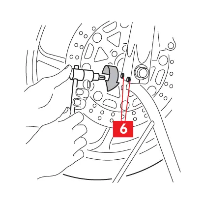
2. Loosen the screws (point 6) on the fork joint feet, on both sides if present, without taking them out.
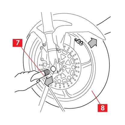
3. Remove the pin (point 7) keeping the wheel (point 8) slightly raised to permit extraction of the pin.
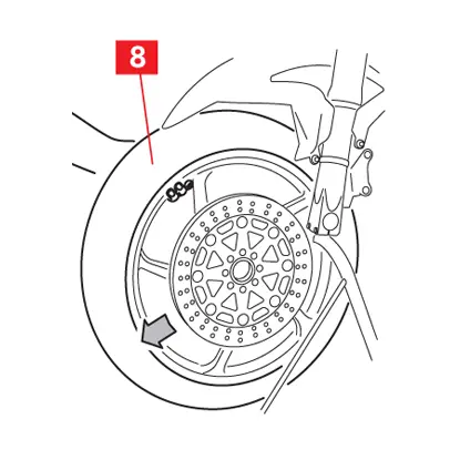
4. Remove the wheel (point 8).
Remove the rear wheel
Follow one of the procedures below depending on the type of rear wheel to be removed.
Traditional wheel
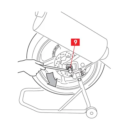
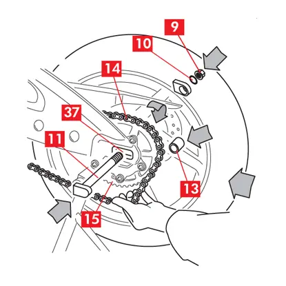
1. Unscrew the nut (point 9) on the pin.
2. Remove nut (point 9) and washer (point 10).
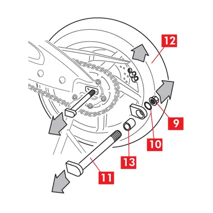
3. Remove the pin (point 11) keeping the wheel (point 12) slightly raised to permit extraction of the pin.
4. Remove the spacer (point 13).
5. Gently push the wheel towards the vehicle.
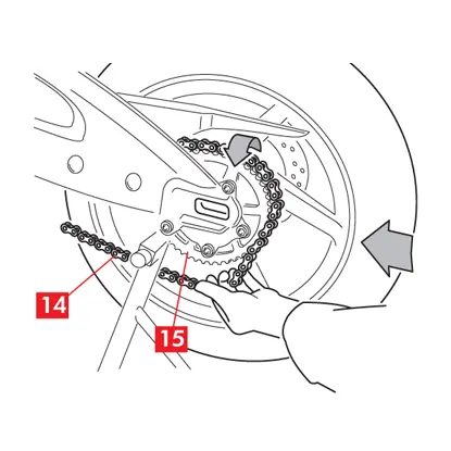
6. Slide the chain (point 14) out of the sprocket (point 15) resting it on its side.
7. Remove the wheel.
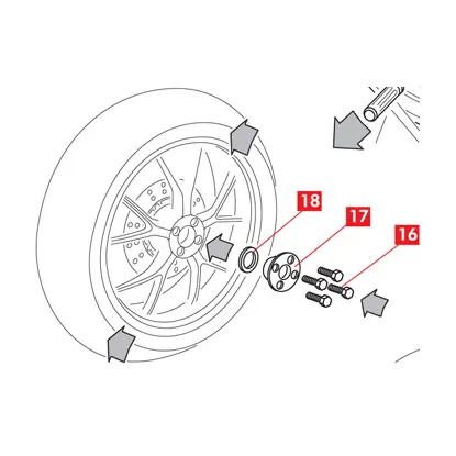
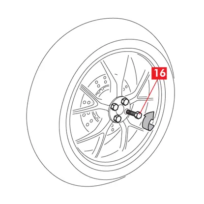
Single-arm wheel with fastening screws
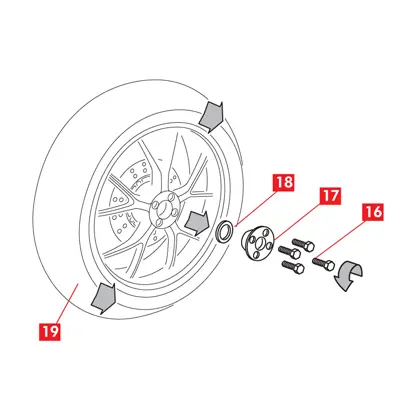
1. Unscrew the fastening screws (point 16).
2. Remove the screws (point 16), the centring ring (point 17), if provided, and any washers (point 18), noting their position to ensure that they are refitted correctly.
3. Remove the wheel (point 19).
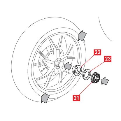
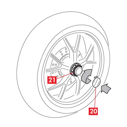
Single-arm wheel with axial nut
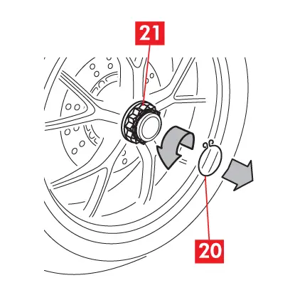
1. Remove the safety ring (point 20), if provided, using a pair of pliers.
2. Unscrew the nut (point 21) on the pin.
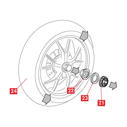
3. Remove nut (point 21), the centring ring (point 22), if provided, and any washers (point 23).
4. Remove the wheel (point 24).
Replacing the brake disc
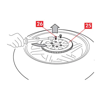
1. Rest the wheel on a work surface.
2. If necessary, remove the sprocket (point 25) from the wheel, unscrewing the fastening screws (point 26).

3. Unscrew and remove the disc fastening screws (point 27).
4. Remove the disc to be replaced (point 28).
5. If replacing the wheel, use the new wheel provided as spare.
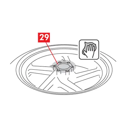
6. Clean the area where the disc rests on the wheel (point 29) using a degreasing product (e.g. solvent SE 47).
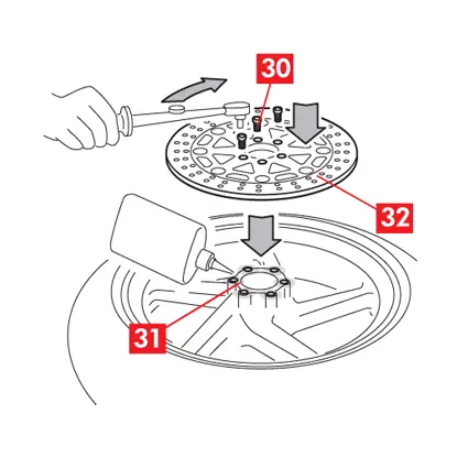
7. If the new screws (point 30) are without thread locker, apply thread locker (e.g. LOCTITE 242) in the seats of the fastening screws (point 31).
8. Position the new disc (point 32).
9. Insert the new fastening screws (point 30) and tighten them with a torque wrench to the following tightening torque:
| Screw type | M8x1.25 | M6x1 |
| Tightening torque | 30 Nm | 14 Nm |
10. Proceed in the same way for replacement the tyre, contact a tyre specialist.
WARNING!
- Ensure that the solvent does not come into contact with parts of the wheel that could be damaged (rubber and paint).
- Use new screws to fasten the disc.
- For correct fixing of the screws, proceed in cross sequence.
- For fitting or replacing the tyre, contact a tyre specialist.
CAUTION! Observe any forward rotation direction indications provided.
Refitting the front wheel
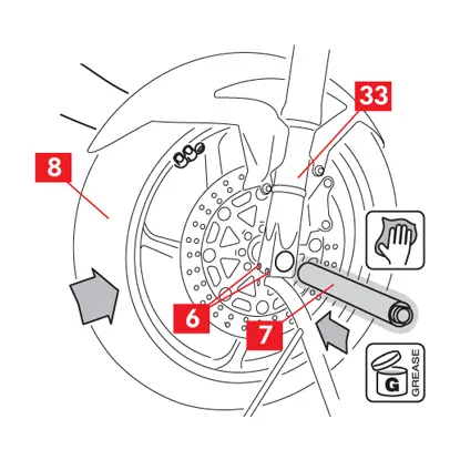
1. Insert the wheel (point 8) in the fork joint (point 33) observing the forward rotation direction indicated on the wheel.
2. Clean with a damp cloth and lubricate the surface of the pin (point 7) to facilitate insertion.
WARNING! Ensure that the solvent does not come into contact with parts of the vehicle that could be damaged (rubber and paint). Promptly absorb with paper.
3. Insert the pin (point 7) keeping the wheel (point 8) in the correct position with one hand and centring the spacer and the milometer transmission, if provided.
4. Position the screws (point 6) of the feet of the fork joint, on both sides if present, only tightening them far enough to keep them in position.
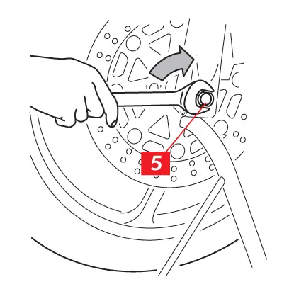
5. Tighten the nut (point 5) on the pin to the torque prescribed by the vehicle manufacturer.
6. Compress the suspension to bed the fork joint.
7. Tighten the screws (point 6) of the fork joint foots using a torque wrench, applying the torque prescribed by the vehicle manufacturer
7. Tighten the screws (point 6) of the fork joint foots using a torque wrench, applying the torque prescribed by the vehicle manufacturer
Refitting the rear wheel
1. Clean the supporting surfaces, all the seats and all the components involved in the refitting operation using a degreasing product (e.g. solvent SE 47).
WARNING! Ensure that the solvent does not come into contact with parts of the vehicle that could be damaged (rubber and paint). Promptly absorb with paper.
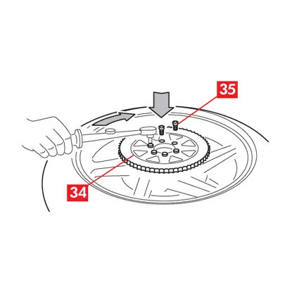
2. If necessary, reposition the sprocket (point 34) on the wheel.
WARNING! Ensure that the solvent does not come into contact with parts of the vehicle that could be damaged (rubber and paint). Promptly absorb with paper.
2. If necessary, reposition the sprocket (point 34) on the wheel.
3. Re-tighten the sprocket fastening screws (point 35), if provided, applying the tightening torque prescribed by the vehicle manufacturer.
Traditional wheel
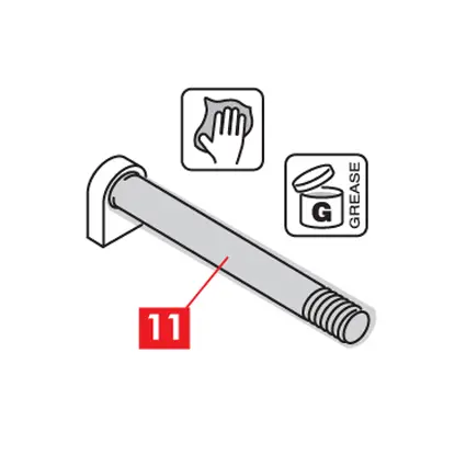
1. Slightly lubricate the surface of the pin (point 11) to facilitate insertion.
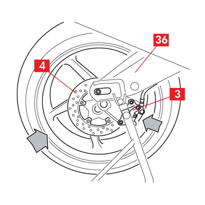
2. Insert the wheel into the fork (point 36).
3. Reposition the caliper (point 3) on the brake disc (point 4).
4. Gently push the wheel towards the vehicle.
3. Reposition the caliper (point 3) on the brake disc (point 4).
4. Gently push the wheel towards the vehicle.
5. Reposition the chain (point 14) on the sprocket (point 15).
6. Correctly reposition the spacer (point 13).
7. Insert the pin (point 11), checking that it fits into the hole provided on the caliper supporting bracket and that the caliper is correctly positioned in its seat on the fork.
8. Check correct positioning of the pin (point 11) in its seat (point 37) on the fork.
9. Correctly repositioning the washer (point 10) and nut.
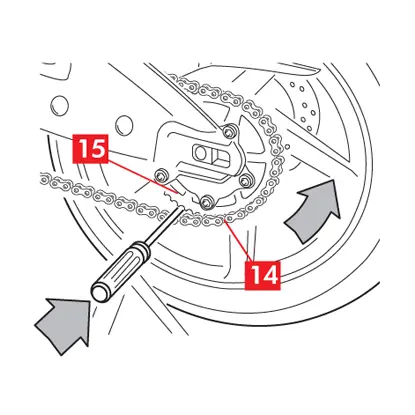
10. Position a shim (e.g. a screwdriver) between the chain (point 14) and the sprocket (point 15).
11. Rotate the wheel far enough to block the shim between the chain and the sprocket.
CAUTION! This operation eliminates the need to tension the chain.
11. Rotate the wheel far enough to block the shim between the chain and the sprocket.
CAUTION! This operation eliminates the need to tension the chain.
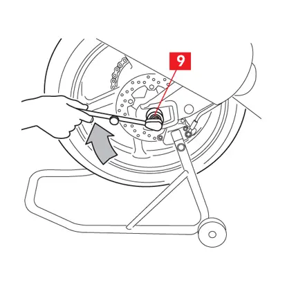
12. Tighten the nut (point 9) on the pin to the tightening torque prescribed by the vehicle manufacturer.
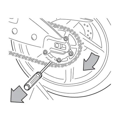
13. Rotate the wheel in the opposite direction and remove the shim.
14. Check correct tensioning of the chain according to the directions provided by the vehicle manufacturer.
Single-arm wheel with fastening screws
1. Reposition the wheel on the supporting surface on the vehicle.
2. Reposition any washers (point 18), any centring ring (point 17) and the fastening screws (point 16).
2. Reposition any washers (point 18), any centring ring (point 17) and the fastening screws (point 16).
3. Tighten the fastening screws (point 16) applying the tightening torque prescribed by the vehicle manufacturer.
WARNING! For correct fastening of the screws, proceed in cross sequence.
WARNING! For correct fastening of the screws, proceed in cross sequence.
Single-arm wheel with axial nut
1. Reposition the wheel on the supporting surface on the vehicle.
2. Reposition any washers (point 23), any centring ring (point 22) and the fastening nut (point 21).
2. Reposition any washers (point 23), any centring ring (point 22) and the fastening nut (point 21).
3. Tighten the fastening nut (point 21) applying the tightening torque prescribed by the vehicle manufacturer.
4. Reposition the safety ring (point 20), if provided.
4. Reposition the safety ring (point 20), if provided.
For all types of wheel
1. If not already done, reposition the caliper or calipers (point 3) on the brake disc (point 4).
2. If the pads obstruct insertion of the caliper on the disc, press firmly with your hands on the pads to retract the pistons.
3. Tighten the fastening screws (point 2) of the caliper or calipers, applying the tightening torque prescribed by the vehicle manufacturer.
4. Use the following approximate tightening torques as a reference:
| Screw type | M10x1.25 | M10x1.25 | M8x1.25 |
| Tightening torque | 50 Nm | 50 Nm | 28 Nm |
5. Check the brake fluid level and top up if necessary with new fluid in compliance with the recommendations of the vehicle manufacturer.
6. Remove the vehicle from the stands.
7. Repeatedly operate the brake lever/pedal until the normal resistance has been restored and check braking efficiency.
General and safety information
This product has been designed to comply with all applicable safety standards. Products are not intended to be used differently from the specific use for which they have been designed and manufactured. Use for any other purpose, or any modification to, or tampering with, the Product can affect the performance of the Product and may render the Product unsafe. Such modification or improper use will void the Limited Warranty, and may subject the individual so using the Product to liability for bodily injury or property damage to others.
As used in these instructions, “DANGER!” means procedures which, if not observed, have a high degree of probability that they will cause serious injury or even death. “WARNING!” means procedures which, if not observed, could possibly cause injury. “CAUTION!” means procedures which, if not observed, could result in damage to the vehicle.
As used in these instructions, “DANGER!” means procedures which, if not observed, have a high degree of probability that they will cause serious injury or even death. “WARNING!” means procedures which, if not observed, could possibly cause injury. “CAUTION!” means procedures which, if not observed, could result in damage to the vehicle.
DANGER!
- This Product is vital to the safe operation of the vehicle on which it is installed, and it is intended to be installed only by a skilled, qualified individual who has been trained and/or is experienced in the installation and use for which the Product is intended.
- The installer must be equipped with the proper tools of his trade, and with the knowledge and experience to deal with vehicle repairs. Improper or incorrect installation, whether caused by a failure to faithfully and completely follow these Instructions or otherwise, will void the Limited Warranty and could subject the installer to liability in the event of personal injury or property damage.
- Brembo shall not be liable for any damage or injury caused to or by any person operating a vehicle on which a replacement product has been improperly installed.
- The used product replaced by this Product must not be installed on any other product. Property damage and personal injury, including death, could result.
- Always check that the brake fluid level in the reservoir is between the minimum and maximum levels indicated on the reservoir. An incorrect level can cause brake fluid leaks or reduced brake system efficiency. Too much or too little brake fluid in the reservoir could cause the brakes not to perform properly, and personal injury, including death, could result.
- Always replace both the brake discs on the axle, using the two discs provided. Every time the discs are changed you should also replace the pads.
- Avoid contact of grease and other lubricants with the braking surfaces of the disc and pads as this could affect the efficiency of the braking system and cause serious physical damage.
WARNING!
- In the course of replacing the product, and related items such as brake fluid, brake pads, brake shoes, and the like, the installer will be exposed to fluids and parts that may be deemed to be “hazardous waste” under applicable laws, rules and regulations. All such wastes must be handles, recycled and(or disposed of in accordance with all applicable laws, rules and regulations. The failure to do so can subject the generator of the hazardous waste to penalties under environmental laws, and could result in bodily injury or property damage to the generator or others.
- To avoid creating a defective installation, avoid sharply striking and /or damaging the Product, its parts and its components, as this can impair their efficiency and may cause them to malfunction. If necessary, replace any damaged part or component.
- To avoid injury:
- Use suitable equipment to prevent the inhalation of dust raised during cleaning of the parts.
- Always wear gloves during disassembly and assembly of components with sharp edges.
- Do not allow skin surfaces to make direct contact between the pad and shoe linings since this could cause abrasions.
- Do not place your hands in the pad locating seat when removing the caliper pistons with aid of compressed air, due to the risk of crushing.
- Avoid direct contact with the brake fluid as it can cause irritation to the skin and eyes. In the event of contact, clean thoroughly in accordance with the vehicle or brake fluid manufacturer’s instructions.
- Do not subject the electrical components to electrostatic charges or to impact which could damage the plastic parts.
- Protect the disassembled electrical components from humidity.
- Ensure correct connection of any electrical contacts, checking that the warning lights come on. If they do not, non-operation of the warning lights can cause a reduction in efficiency of the braking system, or brake signaling failure.
Warranty limitations
This warranty covers all the conformity defects occurring within two years from delivery of the good. The consumer is required to report to the seller the conformity defect within two months from the date of discovery of the said defect, without prejudice to the fact that the limitations period for taking action aimed at seeking redress for the defect is twenty-six months from delivery of the good. In the event of a conformity defect, the user has the right to repair or replacement of the good, or to an appropriate price reduction or termination of the contract, as established by art. 130 of the Consumer Code, where applicable.This warranty constitutes the only warranty provided in relation to this product and replaces any other warranties, both verbal and written.