


Instructions for the replacement of the brake caliper – Motorcycle fixed caliper
Conventions
Before commencing the replacement procedure, ensure that the spare part used for replacement is suitable for the make and model of vehicle.
Identify the figures that are most similar to the model of vehicle and spare part.
Identify the figures that are most similar to the model of vehicle and spare part.
1. Position the vehicle on the stands.
WARNING! During all the phases described below, make sure that the brake fluid does not come into contact with the parts of the vehicle that could be damaged, in particular the painted parts. Immediately absorb with paper and clean with water in the event of splashes or accidental leaks of fluid.
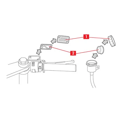
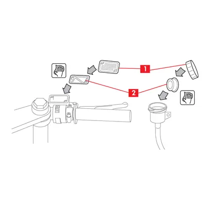
2. Open the plug (point 1) and remove the membrane (point 2) and any diaphragm on the caliper brake fluid reservoir.

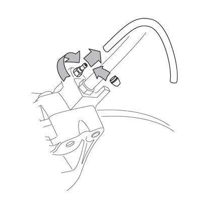
3. Remove the protective cap and connect a transparent tube to the bleed screw (point 3) on the caliper; place a basin under the end of the tube to collect the fluid.
4. Unscrew the bleed screw (point 3) and empty the hydraulic circuit.
5. Close the bleed screw and remove the collecting tube.
4. Unscrew the bleed screw (point 3) and empty the hydraulic circuit.
5. Close the bleed screw and remove the collecting tube.
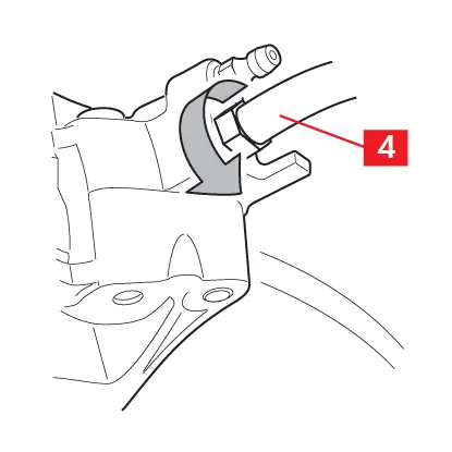
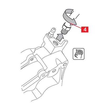
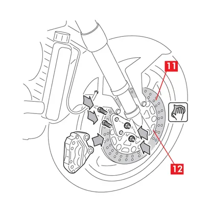
6. Loosen the fluid supply pipe (point 4) on the caliper far enough to permit complete unscrewing by hand to prevent leakage of the brake fluid.
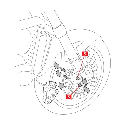
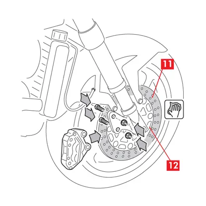
7. Unscrew the fixing bolts (point 5) with an open-end spanner and remove the caliper from the vehicle chassis.
8. Complete detachment of the fluid supply pipe (point 4) from the caliper. Promptly absorb any brake fluid leaks. Keep the supply pipe raised to prevent the fluid leaking out.
9. Remove the caliper to be replaced and rest it on a work surface.
9. Remove the caliper to be replaced and rest it on a work surface.
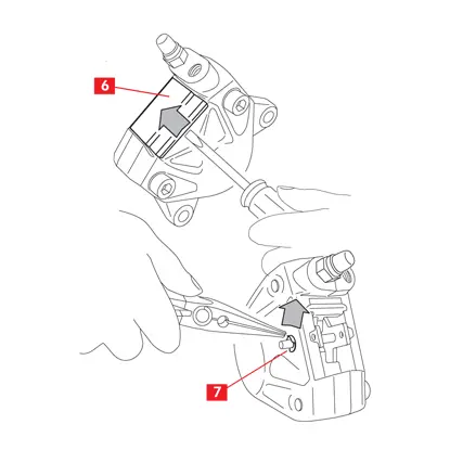
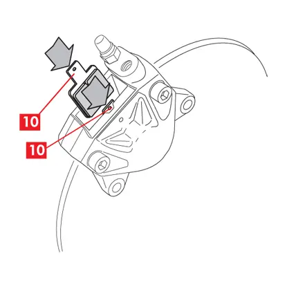
10. For the models provided with dust cover, remove the cover (point 6) using a screwdriver.
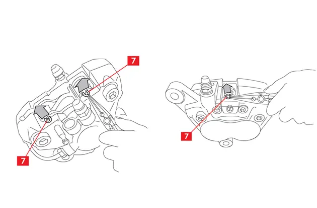
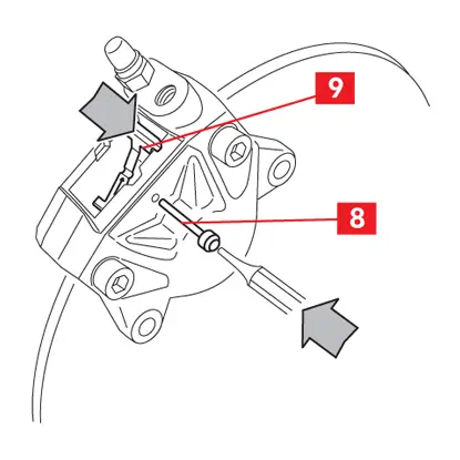
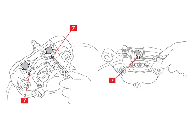
11. For the models provided with retaining clips (point 7) remove them using a pair of pliers.
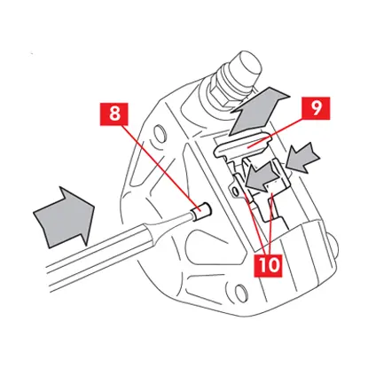
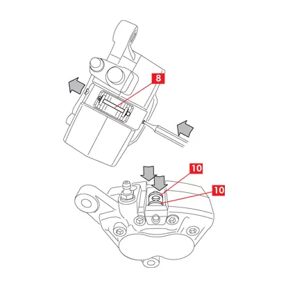
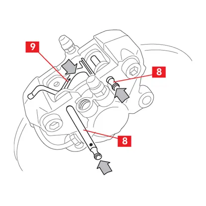
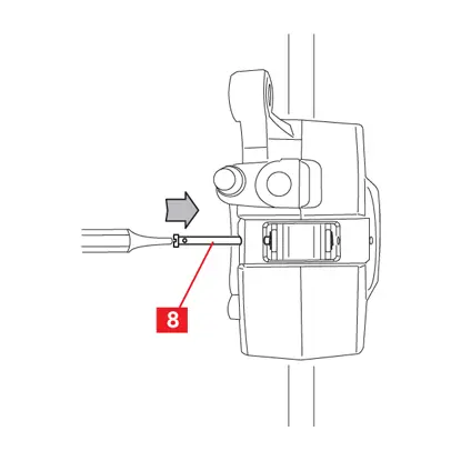
12. Remove the pin or pins (point 8) using a hammer and pin driver if necessary.
13. For calipers with screw-tightened pins, unscrew and remove the pins.
13. For calipers with screw-tightened pins, unscrew and remove the pins.
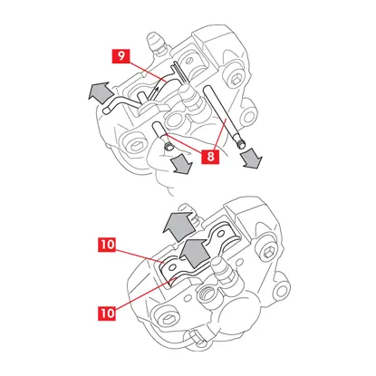
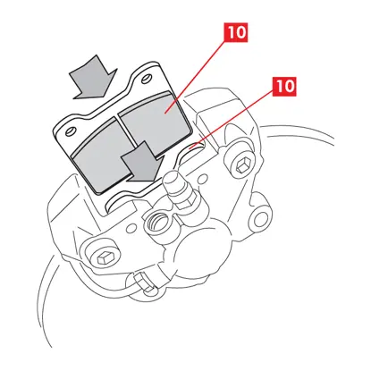
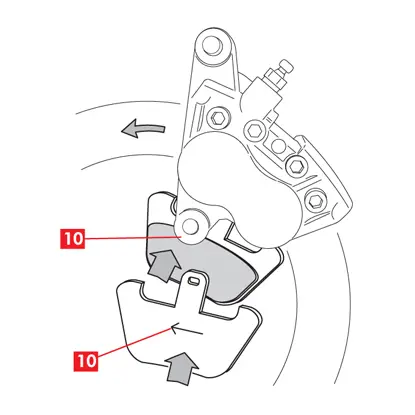
14. Remove the pads (point 10) and also remove the spring (point 9) if necessary.
15. Using a felt pen, mark the disc rotation direction on the pads to ensure correct positioning when refitting.
Fitting the new caliper
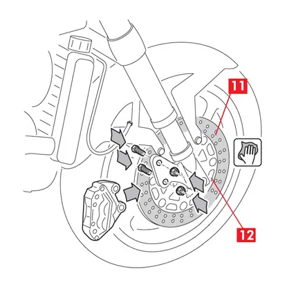
1. Clean the breaking area (point 11) of the disc (point 12) with a degreasing product (e.g. Solvent SE 47).
2. If the caliper is a monobloc caliper, – or if necessary – insert the pads in the new caliper.
3. Position the caliper on the hub carrier.
4. For calipers with radial fitting (screw axis perpendicular to wheel axis),locate the fastening screws. Close the fastening screws by hand, without using spanners or other tools; final closing must be performed after bleeding of the system, as illustrated in this street (see “Fastening caliper with radial fittings”).
4. For calipers with radial fitting (screw axis perpendicular to wheel axis),locate the fastening screws. Close the fastening screws by hand, without using spanners or other tools; final closing must be performed after bleeding of the system, as illustrated in this street (see “Fastening caliper with radial fittings”).
5. For calipers with axial fitting (screw axis parallel to wheel axis), tighten as indicated by the vehicle manufacturer. Alternatively use the following approximate tightening torques as a reference.
| Screw type | Tightening torque |
| M10x1.25 | 50 Nm |
| M10x1.5 | 50 Nm |
| M8x1.25 | 28 Nm |
6. If not done previously, insert the pads (point 10) in the new caliper, housing them correctly in their seats and ensuring that any arrows stamped on them are facing disc rotation direction.
CAUTION! Check the correct positioning of any springs in the pad seats.
DANGER! The pads must be inserted with the friction material facing towards the disc.
DANGER! Ensure that the friction surfaces do not become dirty with grease; all traces of grease must be removed using sandpaper.
DANGER! Ensure that the friction surfaces do not become dirty with grease; all traces of grease must be removed using sandpaper.
7. If not fixed to the pads, reposition the spring (point 9).
CAUTION! The spring is positioned correctly when the pin or pins can be inserted and when any arrows stamped on it are facing in the disc rotation direction.
CAUTION! The spring is positioned correctly when the pin or pins can be inserted and when any arrows stamped on it are facing in the disc rotation direction.
8. Reposition the pin or pins (point 8), keeping the spring (point 9) in position with one hand.
9. Locate the pin or pins (point 8) using the hammer and pin driver. A pin is correctly located when it will go no farther and the sound of the hammer blow is stronger and metallic.
9. Locate the pin or pins (point 8) using the hammer and pin driver. A pin is correctly located when it will go no farther and the sound of the hammer blow is stronger and metallic.
For caliper with screw-tightened pin, tighten the pin to the following torque.
| Pin type | Tightening torque |
| Torx socket | 5÷7 Nm |
| Hexagonal socket | 9÷12 Nm |

10. Refit any clips (point 7).
11. Reposition any dust cover, exerting a slight pressure.
12. Connect the fluid inlet pipe (point 4).
13. Fill the brake fluid reservoir with new fluid according to the vehicle manufacturer’s specifications
13. Fill the brake fluid reservoir with new fluid according to the vehicle manufacturer’s specifications
Bleeding the system on the caliper side
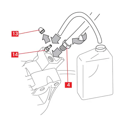
1. Remove the protective cap (point 13) and connect a transparent tube to the bleed screw (point 14) on the caliper; place a basin under the end of the tube to collect the fluid.
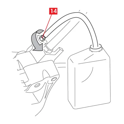
2. Open the bleed screw (point 14).
WARNING! Ensure that the brake fluid does not come into contact with parts of the vehicle that could be damaged, especially the painted parts. Absorb any leaks of brake fluid with paper.
3. Pull/depress the brake lever/pedal.
4. Re-close the bleed screw.
5. Release the brake lever/pedal.
6. Unscrew the bleed screw.
7. Pull/depress the brake lever/pedal again.
8. Repeat the above four points until the usual resistance of the brake lever/pedal has been restored.
4. Re-close the bleed screw.
5. Release the brake lever/pedal.
6. Unscrew the bleed screw.
7. Pull/depress the brake lever/pedal again.
8. Repeat the above four points until the usual resistance of the brake lever/pedal has been restored.
9. Re-close the bleed screw. With the screw closed, remove the fluid collection tube.
10. Tighten the bleed screw applying the approximate tightening torques given in the following table.
10. Tighten the bleed screw applying the approximate tightening torques given in the following table.
| Bleed screw | M6x1 | M8x1,25 | M10x1 | M12x1 |
| Tightening torque | 5÷7 Nm | 7÷10 Nm | 12÷16 Nm | 18÷22 Nm |
11. After bleeding, the brake fluid in the reservoir will be at minimum level. Fully retract the caliper pistons using a suitable tool (e.g. a retractor).
12. Top up the brake fluid in the reservoir if necessary.
13. Thoroughly clean the bleed screw (point 1), the membrane (point 2) and any diaphragm of the brake fluid reservoir.
14. Re-position the membrane (point 2), any diaphragm and re-close the bleed screw (point 1) on the reservoir, re-tightening any fastening screws.
15. Thoroughly clean any brake fluid that has accidentally spilled using a damp cloth.
Fastening calipers with radial fittings
1. Vigorously operate the brake lever/pedal a few times.
2. Keep the brake lever/pedal pulled/depressed so that the system remains pressurized.
3. Tighten the caliper fastening screws with an open-end spanner, applying the tightening torque prescribed by the vehicle manufacturer. Use the tightening torques indicated in point “Fitting the new caliper”.
4. Release the brake lever/pedal.
3. Tighten the caliper fastening screws with an open-end spanner, applying the tightening torque prescribed by the vehicle manufacturer. Use the tightening torques indicated in point “Fitting the new caliper”.
4. Release the brake lever/pedal.
For all types of caliper
1. Simulate a braking operation and check that the rear braking indicator light comes on.
DANGER! If you notice leaks of fluid from the caliper, repeat all the operations described above to ascertain the cause and correct the fault.
2. Remove the vehicle from the stands.
General and safety information
This product has been designed to comply with all applicable safety standards. Products are not intended to be used differently from the specific use for which they have been designed and manufactured. Use for any other purpose, or any modification to, or tampering with, the Product can affect the performance of the Product and may render the Product unsafe.
Such modification or improper use will void the Limited Warranty, and may subject the individual so using the Product to liability for bodily injury or property damage to others.
As used in these instructions, “DANGER!” means procedures which, if not observed, have a high degree of probability that they will cause serious injury or even death. “WARNING!” means procedures which, if not observed, could possibly cause injury. “CAUTION!” means procedures which, if not observed, could result in damage to the vehicle.
DANGER
- This Product is vital to the safe operation of the vehicle on which it is installed, and it is intended to be installed only by a skilled, qualified individual who has been trained and/or is experienced in the installation and use for which the Product is intended.
- The installer must be equipped with the proper tools of his trade, and with the knowledge and experience to deal with vehicle repairs. Improper or incorrect installation, whether caused by a failure to faithfully and completely follow these Instructions or otherwise, will void the Limited Warranty and could subject the installer to liability in the event of personal injury or property damage.
- Brembo shall not be liable for any damage or injury caused to or by any person operating a vehicle on which a replacement product has been improperly installed.
- Avoid contact of grease and other lubricants with the braking surfaces of the disc and pads as this could affect the efficiency of the braking system and cause serious physical damage.
- The used product replaced by this Product must not be installed on any other product. Property damage and personal injury, including death, could result.
- Always check that the brake fluid level in the reservoir is between the minimum and maximum levels indicated on the reservoir. An incorrect level can cause brake fluid leaks or reduced brake system efficiency. Too much or too little brake fluid in the reservoir could cause the brakes not to perform properly, and personal injury, including death, could result.
CAUTION!
Do not use sharp tools when fitting rubber components, since this can damage them. Be sure to replace damaged components.
WARNING!
- To avoid creating a defective installation, avoid sharply striking and/or damaging the Product, its parts and its components, as this can impair their efficiency and may cause them to malfunction. If necessary, replace any damaged part or component.
- In the course of replacing the product, and related items such as brake fluid, brake pads, brake shoes, and the like, the installer will be exposed to fluids and parts that may deemed to be “hazardous waste” under applicable laws, rules and regulations. All such wastes must be handled , recycled and /or disposed of in accordance with all applicable laws, rules and regulations. The failure to do so can subject the generator of the hazardous waste to penalties under environmental laws, and could result in bodily injury or property damage to the generator or others.
- Ensure correct connection of any electrical contacts, checking that the warning lights come on. If they do not, non-operation of the warning lights can cause a reduction in efficiency of the braking system, or brake signaling failure.
- To avoid injury:
- Use suitable equipment to prevent the inhalation of dust raised during cleaning of the parts.
- Always wear gloves during disassembly and assembly of components with sharp edges.
- Do not allow skin surfaces to make direct contact between the pad and shoe lining since this could cause abrasions.
- Do not place your hands in the pad locating seat the removing the caliper pistons with the aid of compressed air, due to the risk of crushing.
- Avoid direct contact with the brake fluid as it can cause irritation to the skin and eyes. In the event of contact, clean thoroughly in accordance with the vehicle or brake fluid manufacturer’s instructions.
- Do not subject the electrical components to electrostatic charges or to impact which could damage the plastic parts.
- Protect the disassembled electrical components from humidity.
Warranty limitations
This warranty covers all the conformity defects occurring within two years from delivery of the good. The consumer is required to report to the seller the conformity defect within two months from the date of discovery of the said defect, without prejudice to the fact that the limitations period for taking action aimed at seeking redress for the defect is twenty-six months from delivery of the good. In the event of a conformity defect, the user has the right to repair or replacement of the good, or to an appropriate price reduction or termination of the contract, as established by art. 130 of the Consumer Code, where applicable.This warranty constitutes the only warranty provided in relation to this product and replaces any other warranties, both verbal and written.
Is there anything else you want to ask?
Contact the Brembo technical support team. Our technicians will get back to you as soon as possible!