


Instrukcje wymiany zacisków hamulcowych w samochodach osobowych i lekkich pojazdach użytkowych
Uważnie przeczytać poniższe instrukcje i przestrzegać ich treści. Te same instrukcje znajdują się w opakowaniu zacisków hamulcowych. Zachować je przez cały cykl eksploatacji produktu. W przypadku sprzedaży pojazdu przekazać je nowemu właścicielowi.
Niniejsze instrukcje montażu stanowią wytyczne dotyczące standardowych prac naprawczych i nie uwzględniają funkcji specjalnych, które mogą mieć zastosowanie w innych układach hamulcowych. Szczegółowo przestrzegać instrukcji specjalnych wydanych przez producenta pojazdu i układu hamulcowego.
W tym miejscu zamieszczono instrukcje wymiany zacisków:
1. Zaciski hamulca jednotarczowego
2. Zaciski stałe hamulca dwutarczowego
3. Zaciski pływające z klockami montowanymi radialnie, typu 2 x 60/68.
2. Zaciski stałe hamulca dwutarczowego
3. Zaciski pływające z klockami montowanymi radialnie, typu 2 x 60/68.
Wszystkie informacje na tym arkuszu instrukcji dotyczą wszystkich trzech typów zacisków, chyba że podano inaczej.
Procedura wymiany
Przed rozpoczęciem wymiany upewnić się, że używane części zamienne są odpowiednie dla danej marki i danego modelu pojazdu.
- Zdjąć koło.
- Zanotować położenie wszystkich częściowo lub całkowicie wymontowanych komponentów, aby umożliwić późniejsze prawidłowe zamontowanie ich na miejscu.
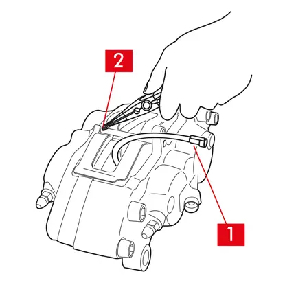
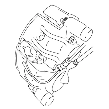
1. Odłączyć przewód wskaźnika zużycia (punkt 1), jeżeli występuje, od końcówki w pojeździe, odłączając go od wszelkich mocowań w podwoziu i na zacisku.
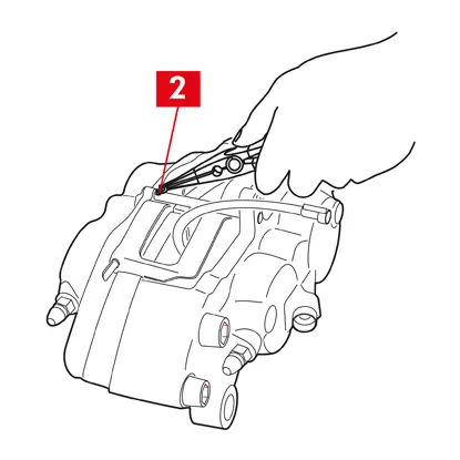
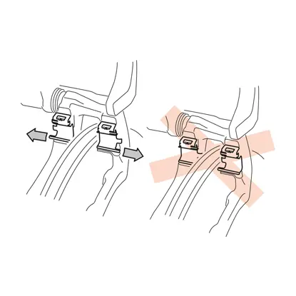
2. W przypadku modeli wyposażonych w zawleczki zabezpieczające (punkt 2) wyjąć je za pomocą szczypiec.

3. W przypadku zacisków podwójnych tarcz szczypcami wyjąć sprężyny (punkt 3).
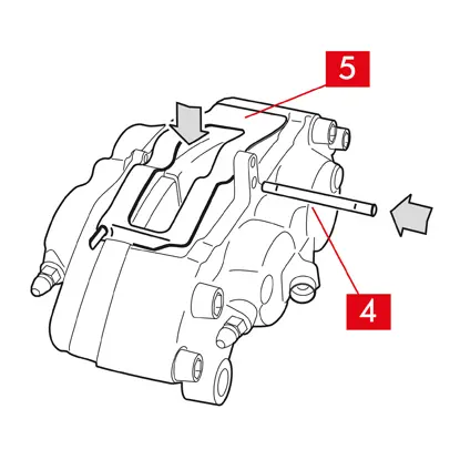
4. Wyjąć sworznie (punkt 4) za pomocą młotka i wybijaka. Wyciągnąć całkowicie ręką i upewnić się, że sprężyny (punkt 5) pozostaną na miejscu.
5. Wyjąć sprężynę/sprężyny (punkt 5). Sprawdzić poziom płynu. Odkręcić korek zbiornika płynu hamulcowego.
PRZESTROGA! Wykonanie opisanej poniżej procedury wycofywania tłoczka spowoduje wzrost poziomu płynu w zbiorniku. Upewnić się, że poziom płynu hamulcowego nie spowoduje wycieku, ponieważ doprowadzi to do uszkodzenia lakierowanych części pojazdu.
ZACISKI STAŁE typu A B
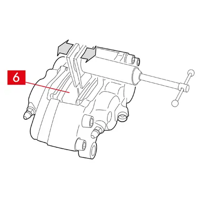
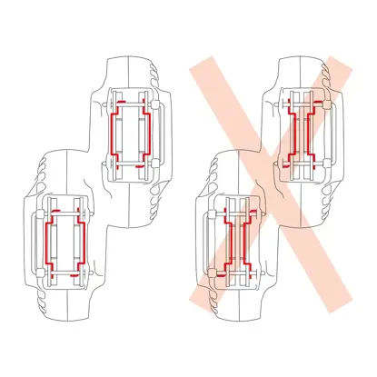
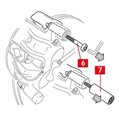
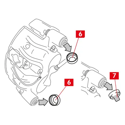
1. Lekko odciągnąć tłoczki za pomocą ściągacza lub innego odpowiedniego narzędzia, naciskając na klocki (punkt 6).
Wycofanie tłoczka musi umożliwić poluzowanie zacisku względem tarczy.
2. Jeżeli pozwala na to konstrukcja zacisku, wyjąć klocki. W przeciwnym razie wyjąć je dopiero po wymontowaniu zacisku. Jeżeli klocki mają zostać użyte ponownie, należy zaznaczyć na nich pisakiem kierunek obrotu tarczy.
ZACISKI PŁYWAJĄCE typu C

1. Wyjąć klocki, jednocześnie przesuwając obudowę zacisku do tyłu i do przodu na tulejach prowadzących (punkt 7). Przesunięcie obudowy zacisku spowoduje nieznaczne odsunięcie klocków od tarczy, co ułatwi ich wyjęcie.
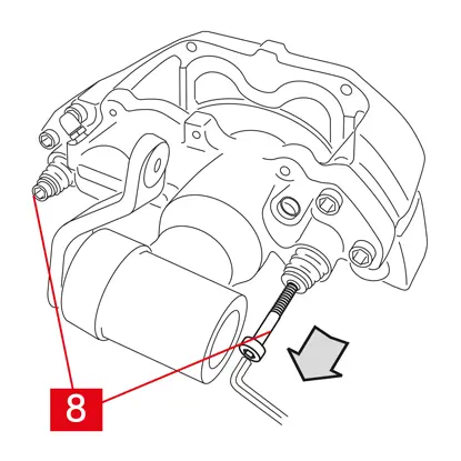
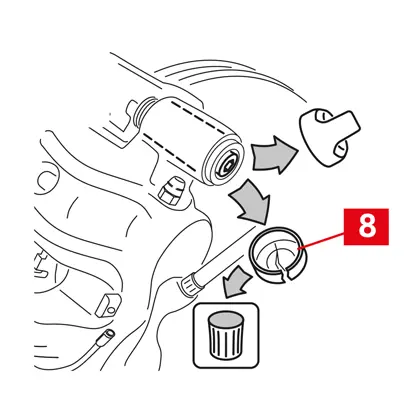
Jeżeli zagłębienie powstałe przez zużycie tarczy utrudnia wyjęcie klocków, należy zdemontować obudowę zacisku:
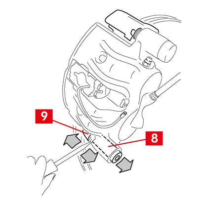
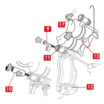
1. Wykręcić śruby (punkt 8) za pomocą klucza płaskiego.
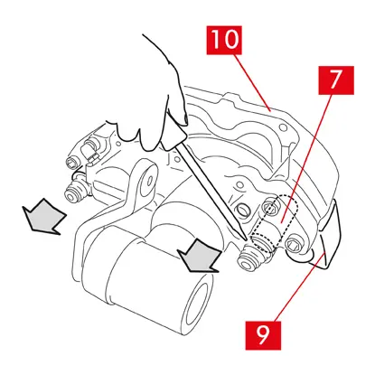
2. Za pomocą śrubokręta podważyć tuleje prowadzące w gniazdach.
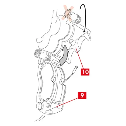
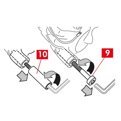
3. Wyjąć tuleje prowadzące (punkt 7) na tyle, aby oddzielić je od wspornika zacisku (punkt 9).
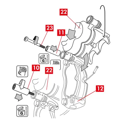
4. Oddzielić całkowicie obudowę zacisku (punkt 10) od wspornika zacisku (punkt 9) i zawiesić na podwoziu pojazdu, używając haczyka w kształcie litery S.
5. Wyjąć klocki.
6. Jeżeli klocki mają zostać użyte ponownie, należy zaznaczyć na nich pisakiem kierunek obrotu tarczy.
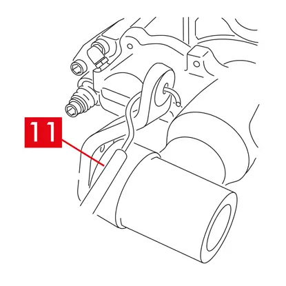
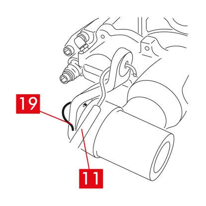
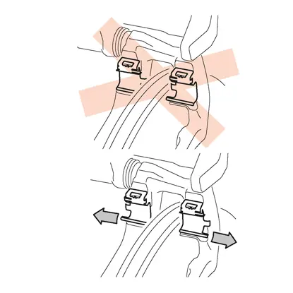
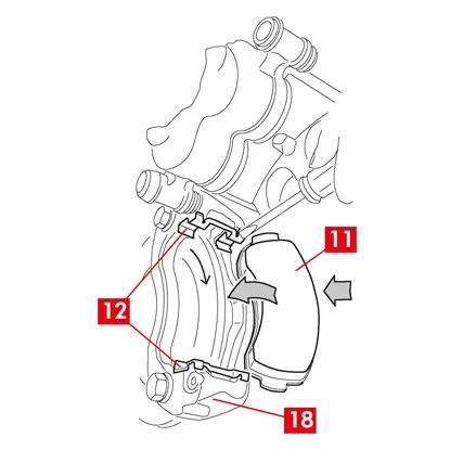
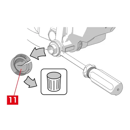
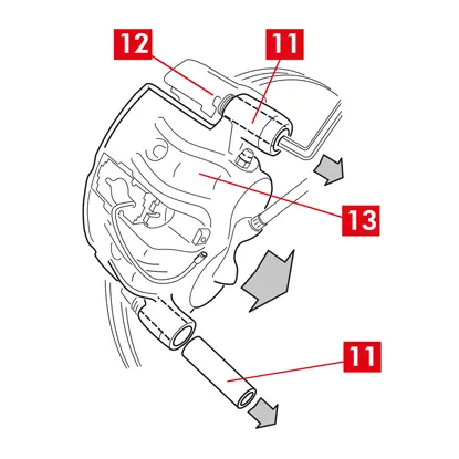
7. W przypadku zacisków tylnych (z mechanizmem hamulca postojowego) odłączyć linkę sterującą hamulca postojowego (punkt 11).
NIEBEZPIECZEŃSTWO! Przewody płynu hamulcowego muszą pozostać luźne, nie mogą być naprężone. Naprężenie przewodów może spowodować ich zerwanie i wyciek płynu hamulcowego.
Dotyczy wszystkich typów zacisków
1. Zakręcić korek zbiornika płynu hamulcowego.
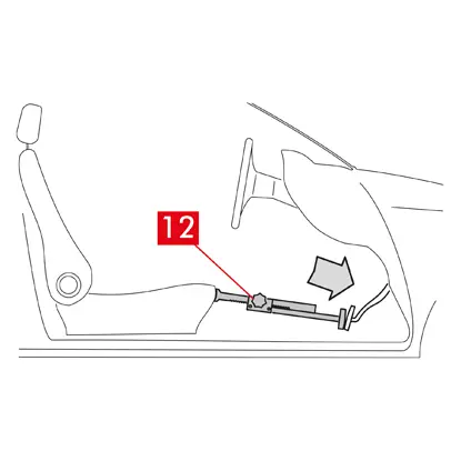
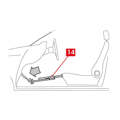
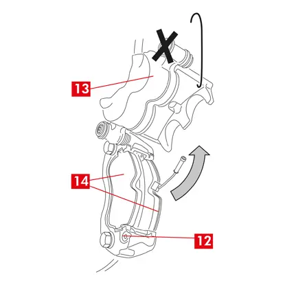
2. We wnętrzu pojazdu umieścić między siedzeniem a pedałem hamulca rozpórkę (punkt 12), aby pedał pozostał wciśnięty podczas wykonywania tych czynności.
OSTRZEŻENIE! Umożliwia to zamknięcie obwodu płynu hydraulicznego i uniknięcie wycieku płynu hamulcowego.
PRZESTROGA! Na każdym opisanym poniżej etapie upewnić się, że płyn hamulcowy nie ma kontaktu z częściami pojazdu, które mogą zostać uszkodzone, szczególnie z elementami lakierowanymi. Natychmiast zetrzeć rozlany płyn ręcznikiem papierowym i wymyć daną powierzchnię wodą.
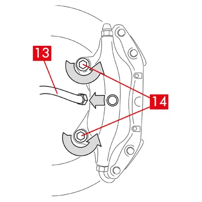
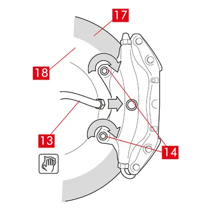
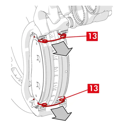
3. Poluzować przewód doprowadzający (punkt 13) na zacisku na tyle, aby móc odkręcić go całkowicie ręką, ale uważać, aby nie doszło do wycieku płynu hamulcowego.
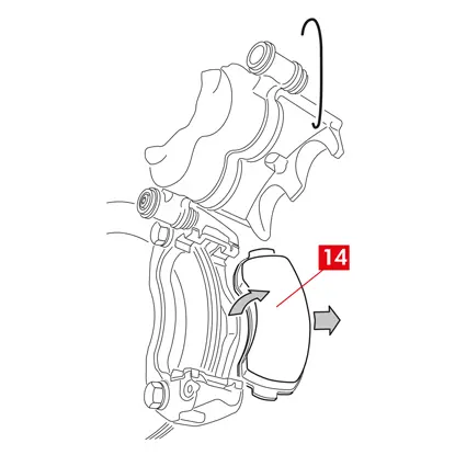
4. Odkręcić śruby mocujące (punkt 14) otwartym kluczem płaskim i zdjąć zacisk z osi.
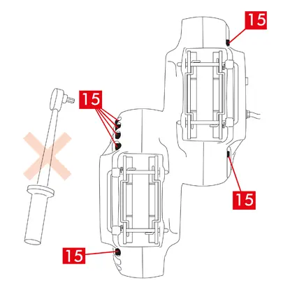
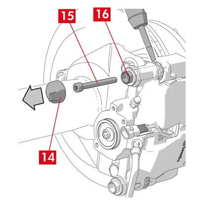
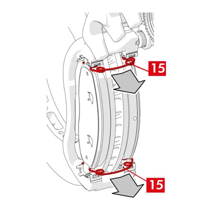
5. PRZESTROGA! W przypadku zacisków podwójnych tarcz odkręcić tylko śruby mocujące do osi. Nie odkręcać śrub (punkt 15) łączących połówki zacisków.
6. Całkowicie odłączyć przewód doprowadzający (punkt 13) od zacisku.
7. Jak najszybciej zetrzeć rozlany płyn hamulcowy.
8. Ustawić przewód doprowadzający w pozycji podniesionej, aby zapobiec przypadkowym wyciekom płynu.
9. Odsunąć zacisk do wymiany.
9. Odsunąć zacisk do wymiany.
Procedura montażu
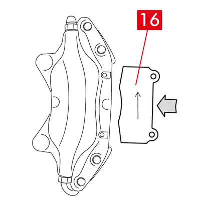
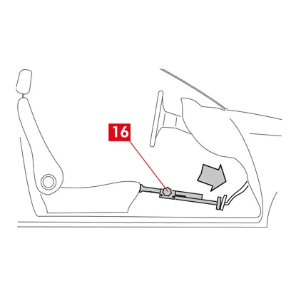
1. Włożyć klocki (punkt 16) do nowego zacisku.
OSTRZEŻENIE! Strzałki umieszczone na klockach muszą być skierowane w kierunku obrotu tarczy.
NIEBEZPIECZEŃSTWO! Włożyć klocki tak, aby materiał cierny był skierowany w stronę tarczy.
2. OSTRZEŻENIE! Jeżeli umożliwia to konstrukcja zacisku, klocki można włożyć także po zamontowaniu zacisku, tuż po wykonaniu etapu„dokręcanie śrub mocujących”.
NIEBEZPIECZEŃSTWO! Upewnić się, że powierzchnie cierne nie są zabrudzone smarem, a jeżeli tak jest, usunąć wszystkie ślady smaru papierem ściernym.
3. Włożyć sprężyny (punkt 5) i sworznie (punkt 4) do odpowiednich gniazd w zacisku i klockach. Sworznie należy wsunąć całkowicie za pomocą młotka i wybijaka.
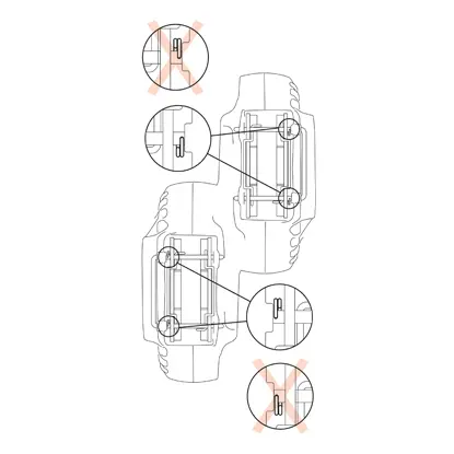
Podczas montażu sprężyn zachować prawidłową orientację.
4. Sprawdzić, czy sprężyny zostały prawidłowo ustawione.
5. W przypadku modeli wyposażonych w zawleczki zabezpieczające (punkt 2) założyć je za pomocą szczypiec.
6. Sprawdzić, czy dzielone zawleczki zostały prawidłowo ustawione.
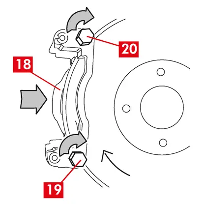
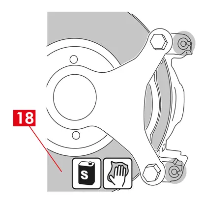
7. Oczyścić powierzchnię hamującą (punkt 17) na tarczy (punkt 18) za pomocą produktu do odtłuszczania (np. rozpuszczalnika SE 47).
8. Założyć nowy zacisk na oś, wkładając tarczę (punkt 18) między klocki.
9. Śruby mocujące (punkt 14) dokręcić otwartym kluczem płaskim momentem zalecanym przez producenta pojazdu.
Można też zastosować poniższe zalecane referencyjne momenty dokręcania:
| Typ śruby | M12x1,25 | M12x1,5 | M14x1,5 |
| Moment dokręcenia | 115 Nm | 125 Nm | 180 Nm |
10. Podłączyć przewód wskaźnika zużycia, jeżeli występuje, do końcówki w pojeździe oraz wszelkich mocowań w podwoziu i na zacisku.
11. Podłączyć przewód doprowadzający płyn hamulcowy (punkt 13).
12. Wyjąć rozpórkę umieszczoną wcześniej we wnętrzu pojazdu, co spowoduje zwolnienie pedału hamulca i ponowne otwarcie obwodu.
13. W przypadku zacisków tylnych typu C (z mechanizmem hamulca postojowego) podłączyć linkę sterującą hamulca postojowego (punkt 11).
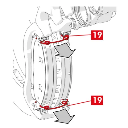
14. Wyjąć sworzeń blokujący dźwignię (punkt 19).
15. Włączyć hamulec postojowy w pojeździe. Powtórzyć proces kilkakrotnie, aż skok dźwigni mechanizmu hamulca osiągnie minimalną wartość.
16. Odkręcić korek zbiornika płynu hamulcowego.
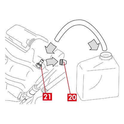
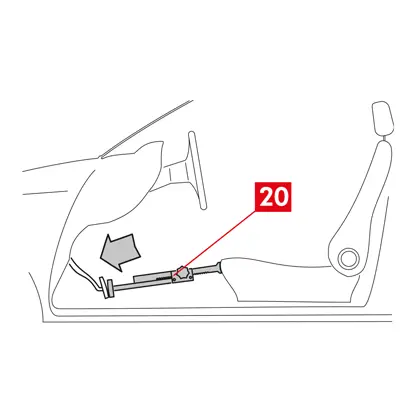
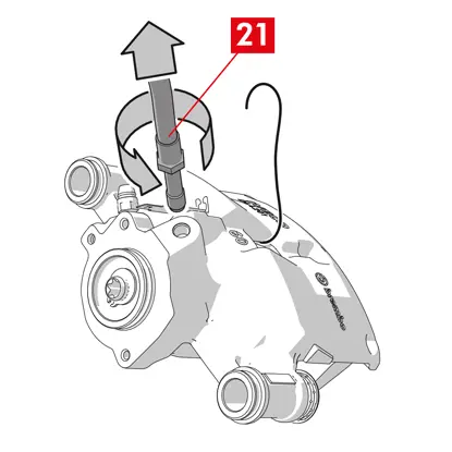
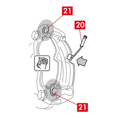
17. Zdjąć osłonę zabezpieczającą (punkt 20) i podłączyć przezroczysty wężyk do korka odpowietrznika (punkt 21) na zacisku, a drugi koniec włożyć do pojemnika, aby zebrać płyn.
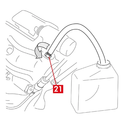
18. Otworzyć korek odpowietrznika (punkt 21).
19. Nacisnąć kilkukrotnie pedał hamulca, aż płyn hamulcowy zacznie wypływać z korka odpowietrznika.
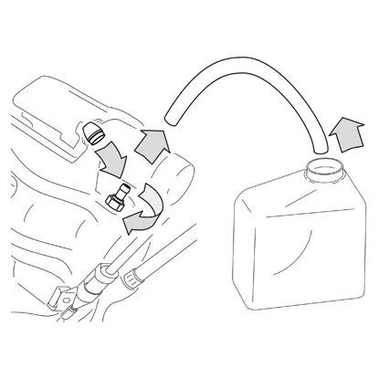
20. Trzymając pedał w pozycji wciśniętej, zamknąć korek odpowietrznika. Zwolnić pedał, poczekać kilka sekund, a następnie powtórzyć procedurę, aż wypływający płyn nie będzie miał żadnych pęcherzyków powietrza i zostanie przywrócony normalny opór oraz zakres ruchu pedału hamulca.
21. Dokręcić korek odpowietrznika momentem podanym w tabeli:
| Korek odpowietrznika | M6x1 | M6x1 | M6x1 | M6x1 |
| Moment dokręcenia | 5÷7 Nm | 7÷10 Nm | 17÷20 Nm | 18÷22 Nm |
22. Wyjąć przezroczysty wężyk i założyć osłonę zabezpieczającą na korek odpowietrznika.
23. Powtórzyć procedurę odpowietrzania dla pozostałych korków odpowietrznika.
24. Po zakończeniu procedury odpowietrzania całkowicie cofnąć tłoczki w zacisku, używając odpowiedniego narzędzia (na przykład ściągacza) i uzupełnić płyn, zgodnie z zaleceniami producenta.
25. Zakręcić korek zbiornika płynu hamulcowego.
26. Przy uruchomionym silniku wcisnąć mocno pedał hamulca i sprawdzić, czy nie występują wycieki płynu z zacisku lub nieprawidłowy spadek ciśnienia w obwodzie, a tylne światła stop włączają się.
NIEBEZPIECZEŃSTWO! Jeżeli płyn wycieka z zacisku, należy powtórzyć wszystkie czynności podane w tym dokumencie, aby określić przyczynę problemu i rozwiązać go.
27. W przypadku zacisków z wbudowanym hamulcem postojowym połączyć końcówkę linki hamulca postojowego z gniazdem w zacisku. Kilkakrotnie zaciągać i zwalniać dźwignię hamulca postojowego we wnętrzu pojazdu.
28. Założyć koło.
29. Jeżeli klocki są nowe, wymagają dotarcia; należy postępować wg instrukcji dostarczonych z klockami zamiennymi.
W tym miejscu zamieszczono instrukcje wymiany zacisków hamulcowych:
Zaciski pływające ze sprężyną centralną
Zaciski pływające z 2 lub 4 sprężynami bocznymi i sprężynami ograniczającymi moment resztkowy.
Wszystkie informacje na tym arkuszu instrukcji dotyczą obu typów zacisków, chyba że podano inaczej.
Procedura wymiany
Przed rozpoczęciem wymiany upewnić się, że używane części zamienne są odpowiednie dla danej marki i danego modelu pojazdu.
- Zdjąć koło
- Zanotować położenie wszystkich częściowo lub całkowicie wymontowanych komponentów, aby umożliwić późniejsze prawidłowe zamontowanie ich na miejscu.
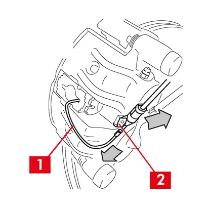
1. Odłączyć wskaźnik zużycia (punkt 1), jeżeli występuje, od końcówki w pojeździe, wyjmując go z podkładki (punkt 2) mocującej do zacisku oraz z wszelkich mocowań na podwoziu.
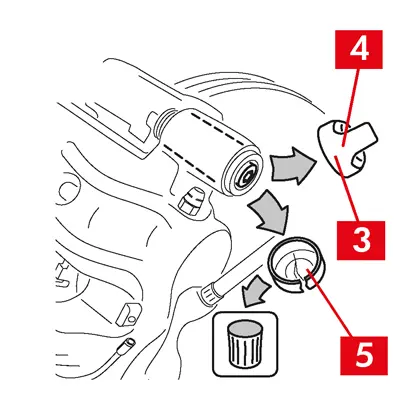
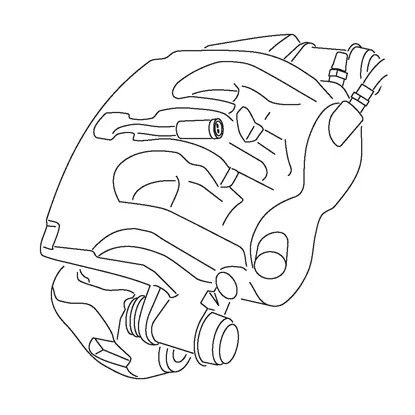
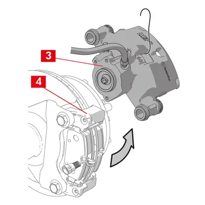
2. Zdjąć osłony zabezpieczające (punkt 3) z tulei prowadzących.
3. Jeżeli osłona posiada wystającą krawędź (punkt 4), należy ściągnąć ją (punkt 4) palcami.
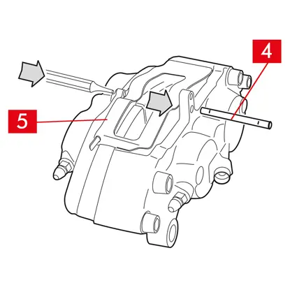
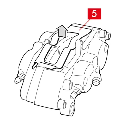
4. Jeżeli osłona jest wykonana z twardego tworzywa sztucznego (punkt 5), należy podważyć ją śrubokrętem. Wyjęcie osłony w taki sposób spowoduje jej pęknięcie.
OSTRZEŻENIE! Nie używać ponownie wymontowanej osłony z tworzyw sztucznych.
PRZESTROGA! Tuleja prowadząca, którą zamierza się wymontować, musi umożliwiać obrócenie obudowy zacisku bez naprężania przewodu doprowadzającego płyn.
OSTRZEŻENIE! Dostępne są dwa typy tulei prowadzących:
- z osobną śrubą
- ze zintegrowaną śrubą
5. Poluzować i całkowicie wykręcić śrubę (punkt 6) lub zintegrowaną tuleję prowadzącą (punkt 7) kluczem płaskim.
OSTRZEŻENIE! Jeżeli do zacisku przyklejone są klocki, należy je rozdzielić za pomocą śrubokręta.
NIEBEZPIECZEŃSTWO! Otwarcie obudowy zacisku może spowodować gwałtowne otwarcie sprężyn ograniczających moment resztkowy.
6. W przypadku tulei prowadzącej bez zintegrowanej śruby (punkt 8) wyciągnąć tuleję prowadzącą ze wspornika zacisku (punkt 9), podważając ją w gnieździe śrubokrętem.
7. W przypadku wymiany zacisku na kołach tylnych z zawieszeniem i resorami piórowymi należy zdjąć dwie tuleje prowadzące (punkt 8), aby całkowicie oddzielić obudowę zacisku (punkt 10) od wspornika zacisku (punkt 9).
8. Odsunąć obudowę zacisku (punkt 10) od wspornika zacisku (punkt 9), obracając ją wokół drugiej tulei prowadzącej, aż klocki wyjdą ze wspornika zacisku. Przymocować obudowę zacisku do podwozia pojazdu za pomocą odpowiednich podpór.

9. Wyjąć klocki (punkt 11) i sprężyny (punkt 12), nie uszkadzając ich, aby zamontować je na nowym zacisku.
10. Za pomocą pisaka oznaczyć kierunek obrotu tarczy na klockach, aby uniknąć ich nieprawidłowego zamontowania.
11. Jeżeli nadal są na swoim miejscu, należy wyjąć sprężyny ograniczające moment resztkowy (punkt 13).
12. We wnętrzu pojazdu umieścić między siedzeniem a pedałem hamulca rozpórkę (punkt 14), aby pedał pozostał wciśnięty podczas wykonywania tych czynności.
OSTRZEŻENIE! Umożliwia to zamknięcie obwodu płynu hydraulicznego i uniknięcie wycieku płynu hamulcowego.
PRZESTROGA! Na każdym opisanym poniżej etapie upewnić się, że płyn hamulcowy nie ma kontaktu z częściami pojazdu, które mogą zostać uszkodzone, szczególnie z elementami lakierowanymi. Natychmiast zetrzeć rozlany płyn hamulcowy ręcznikiem papierowym i wymyć powierzchnię wodą.

13. Poluzować przewód doprowadzający (punkt 15) na zacisku na tyle, aby móc odkręcić go całkowicie ręką, ponieważ zapobiegnie to wyciekaniu płynu hamulcowego.
14. Odkręcić śruby mocujące (punkt 16) otwartym kluczem płaskim i zdjąć wspornik zacisku (punkt 9) ze wspornika piasty.
15. Całkowicie odłączyć przewód doprowadzający (punkt 15) od obudowy zacisku.
16. Jak najszybciej zetrzeć rozlany płyn hamulcowy.
17. Ustawić przewód doprowadzający w pozycji podniesionej, aby zapobiec wyciekom płynu.
18. W przypadku zacisków z wbudowanym hamulcem postojowym odłączyć przewód hamulca postojowego od gniazda w zacisku.
19. Odsunąć zacisk do wymiany.
20. Oczyścić powierzchnie hamujące (punkt 17) na tarczy za pomocą produktu do odtłuszczania (np. rozpuszczalnika SE47).
Procedura montowania zacisku
PRZESTROGA! Nie zdejmować osłony zabezpieczającej z otworu wlotowego płynu na nowym zacisku do momentu przyłączenia do niego przewodu doprowadzającego.
Przed zamontowaniem nowego zacisku nasmarować tuleje i pokrywy przeciwpyłowe dostarczonym smarem.
OSTRZEŻENIE! EUH210 — karta charakterystyki dostępna na życzenie.
OSTRZEŻENIE! EUH208 — zawiera N-alkilowany benzotriazol. Może wywołać reakcję alergiczną.
1. Zdjąć osłony zabezpieczające z tulei, jeżeli występują.
2. Poluzować śruby lub tuleje prowadzące ze zintegrowaną śrubą.
3. W przypadku osobnych śrub całkowicie je wyjąć.
4. Odsunąć obudowę zacisku od wspornika zacisku.
OSTRZEŻENIE! Aby uniknąć uszkodzenia pokryw przeciwpyłowych, należy wyjąć tuleje z boku pokrywy.
5. Zdjąć pokrywy.
6. Dokładnie wyczyścić wszystkie montowane komponenty, gniazda tulei i gniazda w pokrywie za pomocą odpowiednich produktów (np. wilgotnej ściereczki).
7. Wyczyścić powierzchnie montażowe na wsporniku piasty.
8. Ustawić nowy wspornik zacisku (punkt 18), wkładając go do tarczy.
9. Włożyć i częściowo wkręcić dwie śruby mocujące (punkty 19 i 20).
10. Śrubę mocującą po stronie wejściowej tarczy (punkt 19) (po wybraniu biegu jazdy do przodu) dokręcić momentem dokręcania zalecanym przez producenta pojazdu.
11. Drugą śrubę mocującą 20 (po stronie wyjściowej tarczy) dokręcić momentem dokręcania zalecanym przez producenta pojazdu.
Zastosować poniższe zalecane referencyjne momenty dokręcania:
| Typ śruby | Moment dokręcenia |
| M12x1,25 | 115 Nm |
| M12x1,5 | 125 Nm |
| M14x1,5 | 180 Nm |
| M16x1,5 | 210 Nm |
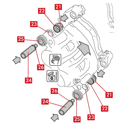
12. Nasmarować równo całą powierzchnię wewnętrzną pokryw (punkt 21) i profil styku (punkt 22) z obudową zacisku.
13. Włożyć pokrywy (punkt 21) do gniazd (punkt 23) na obudowie zacisku.
PRZESTROGA! Sprawdzić palcem, czy pokrywa została prawidłowo włożona i osadzona w obudowie zacisku.
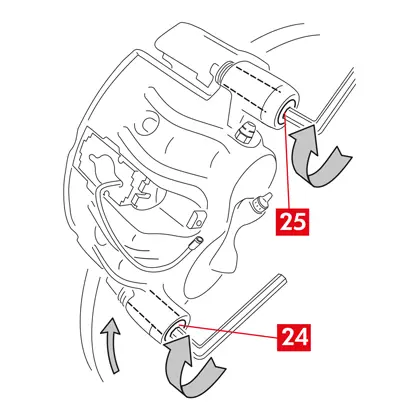
14. Nasmarować powierzchnię zewnętrzną tulei (punkt 24) i jej gniazda (punkt 25) w obudowie zacisku, włożyć tuleje do obudowy zacisku od strony przeciwnej do pokrywy.
15. Wepchnąć tuleje (punkt 24), aż pokrywy (punkt 21) dopasują się do gniazd (punkt 26).
16. Usunąć nadmiar smaru.
17. Założyć całkowicie obudowę zacisku na wspornik zacisku i wkręcić na śrubę lub zintegrowaną tuleję po stronie wyjściowej tarczy (po wybraniu biegu jazdy do przodu).
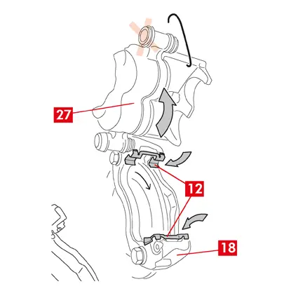
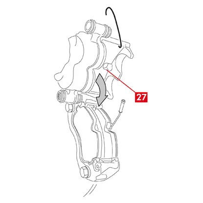
18. Odsunąć obudowę zacisku (punkt 27) od wspornika zacisku (punkt 18), obracając ją wokół tulei prowadzącej, aż klocki wejdą do wspornika zacisku. Przymocować obudowę zacisku do podwozia pojazdu za pomocą odpowiednich podpór.
PRZESTROGA! Nie wykorzystywać jako punktu mocowania gniazda tulei prowadzącej.
Montowanie klocków
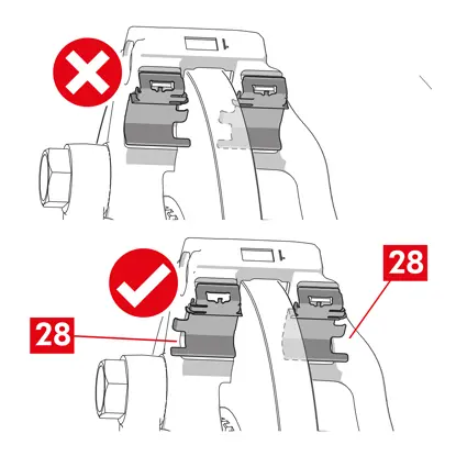
1. Jeżeli są dostępne, sprężyny boczne (punkt 12) należy włożyć do wspornika zacisku, wywierając nacisk odpowiedni do prawidłowego zamocowania.
2. W przypadku zacisków z czterema sprężynami zawsze zakładać sprężyny tak, aby wypustki były skierowane na zewnątrz wspornika zacisku.
PRZESTROGA! Zamontować we właściwym kierunku.
OSTRZEŻENIE! Jeżeli dostępne są klocki ze stroną przylepną, należy zamontować nowe klocki; postępować według instrukcji dostarczonych z nowymi klockami.
PRZESTROGA! Klocek ze wskaźnikiem zużycia musi zostać umieszczony w pierwotnym położeniu, w jakim znajdował się, zanim został wymontowany..
3. Włożyć klocki (punkt 11) do wspornika zacisku (punkt 18); w przypadku zacisków typu B użyć śrubokręta, aby podważyć sprężyny boczne (punkt 12).
OSTRZEŻENIE! Strzałki umieszczone na klockach muszą być skierowane w kierunku obrotu tarczy.
NIEBEZPIECZEŃSTWO! Włożyć klocki tak, aby materiał cierny był skierowany w stronę tarczy.
OSTRZEŻENIE! Strzałki umieszczone na klockach muszą być skierowane w kierunku obrotu tarczy.
NIEBEZPIECZEŃSTWO! Włożyć klocki tak, aby materiał cierny był skierowany w stronę tarczy.
4. Przeprowadzić przewód wskaźnika zużycia (punkt 1) przez odpowiedni kanał w następujący sposób:
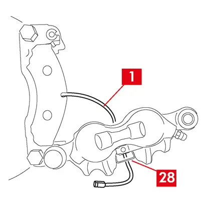
W przypadku zacisków typu A — w sprężynie (punkt 28).
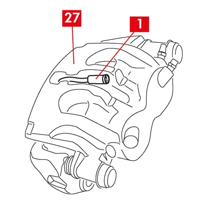
W przypadku zacisków typu B — w obudowie zacisku (punkt 27).
4. Ostrożnie zamknąć zacisk, obracając jego obudowę (punkt 27) wokół nakręconej tulei prowadzącej. Jeżeli dostępne są klocki ze stroną przylepną, należy uważać, aby nie zetknąć obudowy zacisku i klocka przed zamontowaniem obudowy zacisku.
PRZESTROGA! Ostrożnie zamknąć zacisk i sprawdzić, czy pokrywy zabezpieczające na tulejach nie zostały uszkodzone, stukając o wspornik zacisku.
PRZESTROGA! Ostrożnie zamknąć zacisk i sprawdzić, czy pokrywy zabezpieczające na tulejach nie zostały uszkodzone, stukając o wspornik zacisku.
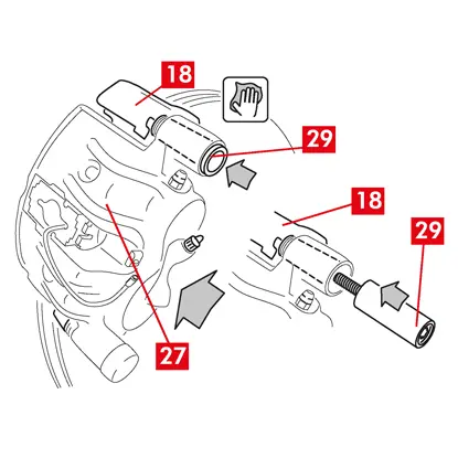
5. Przesunąć obudowę zacisku (punkt 27) w kierunku wspornika zacisku (punkt 18).
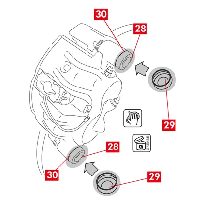
6. Włożyć tuleję prowadzącą (punkt 29) do gniazda wspornika zacisku.
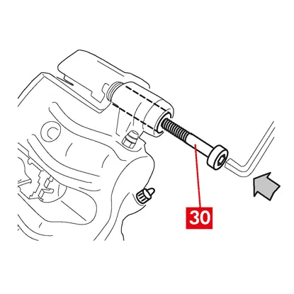
7. Włożyć i wkręcić nową śrubę (punkt 30), jeżeli występuje.

8. W przypadku wymiany zacisku na tylnych kołach z zawieszeniem i resorami piórowymi należy umieścić obudowę zacisku (punkt 27) na wsporniku zacisku (punkt 18), a następnie włożyć obie tuleje prowadzące (punkt 29) oraz włożyć i dokręcić dwie nowe śruby (punkt 30), jeżeli występują.
9. Jeżeli nie jest jeszcze wkręcona, należy dokręcić śrubę mocującą tulei prowadzącej lub wbudowaną tuleję prowadzącą po stronie wejściowej tarczy (po wybraniu biegu jazdy do przodu). Następnie dokręcić tym samym momentem drugą śrubę lub drugą zintegrowaną tuleję prowadzącą.
10. Dokręcić momentem podanym w poniższej tabeli:
| Typ | Moment dokręcenia | |
| Śruba mocująca | (M8 – CH6) | 32 ÷ 36 Nm |
| Tuleja prowadząca ze zintegrowaną śrubą | (M8 – CH6) | 32 ÷ 36 Nm |
| Tuleja prowadząca ze zintegrowaną śrubą | (M10 – CH8) | 65 ÷ 75 Nm |
NIEBEZPIECZEŃSTWO! Dokręcać według podanej kolejności; nieprzestrzeganie tej instrukcji może uniemożliwić prawidłowe działanie zacisku.
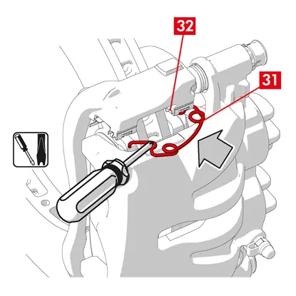
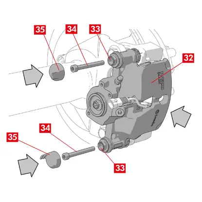
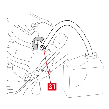
11. W przypadku sprężyn ograniczających moment resztkowy (punkt 31) należy zaczepić sprężynę pod płytką (punkt 32) i zaczepić spodnią część płytki na drugim klocku za pomocą śrubokręta typu U.
NIEBEZPIECZEŃSTWO! Nieprawidłowe przymocowanie sprężyny może spowodować jej gwałtowne otwarcie się.
PRZESTROGA! Zamontować we właściwym kierunku.
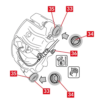
12. Ostrożnie oczyścić części (punkt 33), aby upewnić się, że pozostaną na miejscu i założyć nowe osłony zabezpieczające (punkt 34), nasmarować ich powierzchnię wewnętrzną oraz gniazdo obudowy zacisku smarem dostarczonym w zestawie części zapasowych.
13. Obrócić osłonę zabezpieczającą (punkt 34) tak, aby całkowicie przylegała do gniazda (punkt 35).
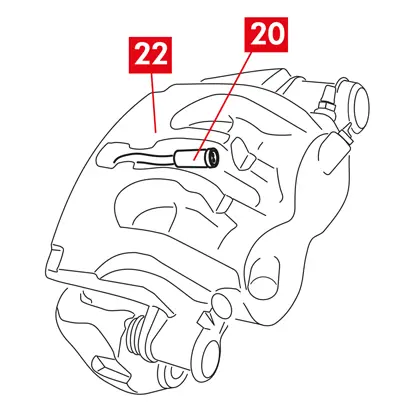
14. Podłączyć z powrotem wskaźnik zużycia, jeżeli występuje, do końcówki w pojeździe, i lekko naciskając przymocować do podkładki na zacisku oraz do wszelkich mocowań w podwoziu.
15. Zdjąć osłonę zabezpieczającą z otworu wlotowego płynu hamulcowego (punkt 36).
16. Podłączyć z powrotem przewód doprowadzający płyn hamulcowy.
17. Wyjąć rozpórkę umieszczoną wcześniej we wnętrzu pojazdu, co spowoduje zwolnienie pedału hamulca i ponowne otwarcie obwodu hydraulicznego.
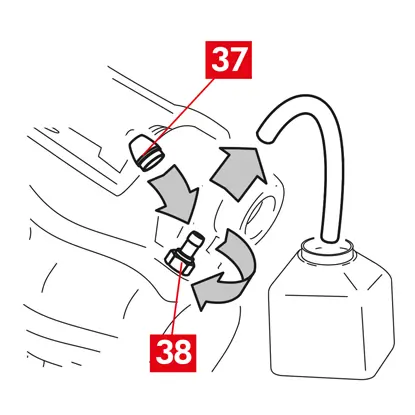
18. Odkręcić korek zbiornika płynu hamulcowego.
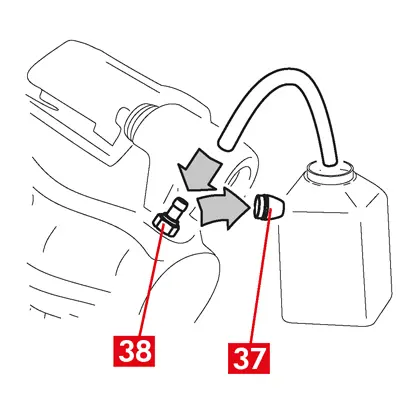
19. Zdjąć osłonę zabezpieczającą (punkt 37) i podłączyć przezroczysty wężyk do korka odpowietrznika (punkt 38) na zacisku, a drugi koniec włożyć do pojemnika, aby zebrać płyn.
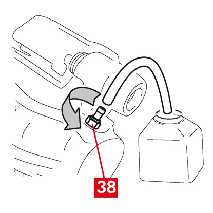
20. Otworzyć korek odpowietrznika (punkt 38).
21. Nacisnąć kilkukrotnie pedał hamulca, aż płyn hamulcowy zacznie wypływać z korka odpowietrznika.
22. Trzymając pedał w pozycji wciśniętej, zamknąć korek odpowietrznika. Zwolnić pedał, poczekać kilka sekund, a następnie powtórzyć procedurę, aż wypływający płyn nie będzie miał żadnych pęcherzyków powietrza i zostanie przywrócony normalny opór oraz zakres ruchu pedału hamulca.
23. Dokręcić korek odpowietrznika momentem podanym w tabeli:
| Korek odpowietrznika | M6x1 | M8x1,25 | M10x1 | M12x1 |
| Moment dokręcenia | 5÷7 Nm | 7÷10 Nm | 17÷20 Nm | 18÷22 Nm |
24. Wyjąć przezroczysty wężyk i założyć osłonę zabezpieczającą na korek odpowietrznika.
25. Powtórzyć procedurę odpowietrzania dla pozostałych korków odpowietrznika.
26. Po zakończeniu procedury odpowietrzania całkowicie cofnąć tłoczki w zacisku, używając odpowiedniego narzędzia (na przykład ściągacza) i uzupełnić płyn, zgodnie z zaleceniami producenta.
27. Zakręcić korek zbiornika płynu hamulcowego.
28. Przy uruchomionym silniku wcisnąć mocno pedał hamulca i sprawdzić, czy nie występują wycieki płynu z zacisku lub nieprawidłowy spadek ciśnienia w obwodzie, a tylne światła stop włączają się.
NIEBEZPIECZEŃSTWO! Jeżeli płyn wycieka z zacisku, należy powtórzyć wszystkie czynności podane w tym dokumencie, aby określić przyczynę problemu i rozwiązać go.
29. W przypadku zacisków z wbudowanym hamulcem postojowym połączyć końcówkę linki hamulca postojowego z gniazdem w zacisku.
30. Kilkakrotnie zaciągać i zwalniać dźwignię hamulca postojowego we wnętrzu pojazdu.
31. Założyć koło.
32. Jeżeli klocki są nowe, wymagają dotarcia; należy postępować wg instrukcji dostarczonych z klockami zamiennymi.
W tym miejscu zamieszczono instrukcje wymiany komponentów zacisków pływających pojazdów użytkowych (typ ECS53 i ECS60) z wbudowanym mechanizmem elektrycznego hamulca postojowego:
1. Moduł urządzenia uruchamiającego
2. Klocki
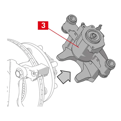
3. Obudowa zacisku (bez klocków i wspornika zacisku)
4. Wspornik zacisku
2. Klocki
3. Obudowa zacisku (bez klocków i wspornika zacisku)
4. Wspornik zacisku
OSTRZEŻENIE! Przed wymianą części zamiennych zawartych w tym zestawie należy przeczytać niniejszy dokument. Wykonać tylko czynności wymagane do wymiany części zamiennych zawartych w tym zestawie.
Procedura wymiany
Przed rozpoczęciem wymiany upewnić się, że używane części zamienne są odpowiednie dla danej marki i danego modelu pojazdu.
OSTRZEŻENIE! W przypadku usterki elektrycznej wymontować moduł urządzenia uruchamiającego i wycofać tłoczek, obracając śrubę typu torx w kierunku zgodnym z ruchem wskazówek zegara, posługując się odpowiednim kluczem płaskim.
- Zanotować położenie wszystkich częściowo lub całkowicie wymontowanych komponentów, aby umożliwić późniejsze prawidłowe zamontowanie ich na miejscu.
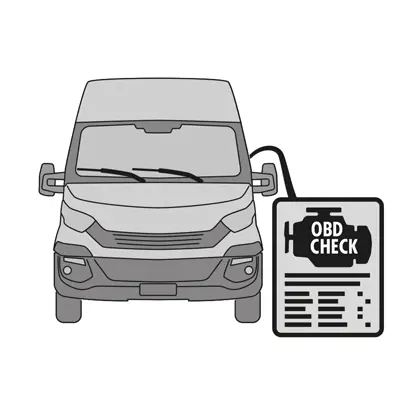
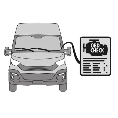
1. Podłączyć do pojazdu przyrząd diagnostyczny (diagnostyka pojazdu — OBD) i przejść do trybu serwisowego zgodnie z opisem producenta pojazdu.
PRZESTROGA! Upewnić się, że część zamienna jest zgodna z oprogramowaniem pojazdu.
2. Zdjąć koło.
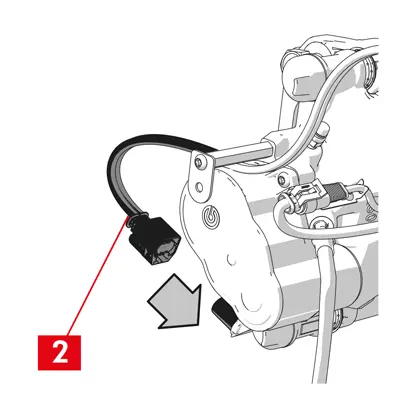
3. Odczepić kabel zasilający modułu urządzenia uruchamiającego od dławika.
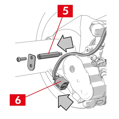
4. W przypadku zacisku typu ECS60 poluzować i zdjąć dławik (punkt 5).
5. Odłączyć kabel zasilania (punkt 6) od modułu urządzenia uruchamiającego.
OSTRZEŻENIE! Złącze można zamocować za pomocą zatrzasku zabezpieczającego.
OSTRZEŻENIE! Złącze można zamocować za pomocą zatrzasku zabezpieczającego.
Wymontowywanie modułu urządzenia uruchamiającego
OSTRZEŻENIE! Wymontowanie modułu urządzenia uruchamiającego należy przeprowadzić tylko wtedy, gdy dostępna jest część zapasowa.
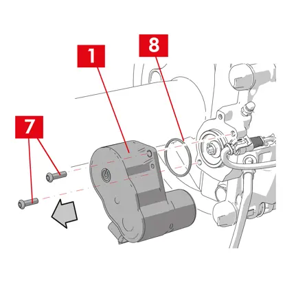
1. Poluzować śruby mocujące (punkt 7) z modułu urządzenia uruchamiającego (punkt 1).
2. Wyjąć moduł urządzenia uruchamiającego (punkt 1).
3. Zdjąć uszczelkę (punkt 8).
Wymontowywanie klocków
PRZESTROGA! Zachować ostrożność, aby nie uszkodzić komponentów, które mają zostać użyte ponownie.
NIEBEZPIECZEŃSTWO! Nie dopuszczać do naprężenia przewodu doprowadzającego płyn hamulcowy.
NIEBEZPIECZEŃSTWO! Nie dopuszczać do naprężenia przewodu doprowadzającego płyn hamulcowy.
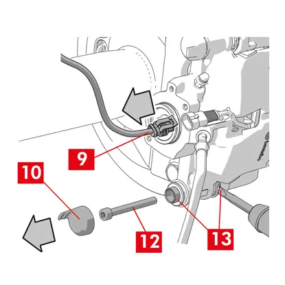
1. Odłączyć wskaźnik zużycia (punkt 9), jeżeli występuje, od końcówki w pojeździe, wyjmując go z podkładki mocującej go do zacisku oraz ze wszelkich mocowań w podwoziu.
2. Zdjąć osłonę zabezpieczającą (punkt 10) z tulei dodatkowej (strona wyjściowa tarczy obracającej się w układzie napędowym na koła przednie).
3. Jeżeli osłona jest wykonana z twardego tworzywa sztucznego (punkt 11), należy podważyć ją śrubokrętem. Wyjęcie osłony w taki sposób spowoduje jej pęknięcie.
OSTRZEŻENIE! Nie używać ponownie wymontowanej osłony z tworzyw sztucznych.
4. Poluzować i wykręcić śrubę dodatkową (punkt 12).
5. W przypadku zacisku typu ECS60 użyć śrubokręta, aby podważyć i wyjąć tuleję z rowka i wspornika zacisku.
6. Zdjąć osłonę zabezpieczającą (punkt 14) z tulei głównej (strona wejściowa tarczy obracającej się w układzie napędowym na koła przednie).
7. Poluzować całkowicie śrubę główną (punkt 15) i wykręcić ją.
OSTRZEŻENIE! Za pomocą śrubokręta podważyć tuleje prowadzące w rowkach.
8. Wyjąć główną tuleję prowadzącą (punkt 16) na tyle, aby zwolnić ją ze wspornika zacisku.
9. Wyciągnąć obudowę zacisku (punkt 3) ze wspornika zacisku (punkt 4), uważając, aby nie naprężyć przewodu doprowadzającego płyn hamulcowy.
10. Przymocować obudowę zacisku do podwozia pojazdu za pomocą odpowiednich podpór.
PRZESTROGA! Nie używać gniazda tulei jako punktu mocowania.
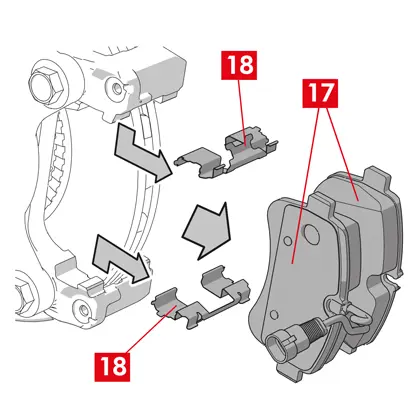
11. Wyjąć klocki (punkt 17) i sprężyny (punkt 18), nie uszkadzając ich, aby zamontować je na nowym zacisku.
12. Jeżeli nadal są na swoim miejscu, należy wyjąć sprężyny ograniczające moment resztkowy (punkt 19).
OSTRZEŻENIE! W celu zamontowania na miejscu tych samych klocków należy oznaczyć je strzałkami (jeżeli nie występują) za pomocą pisaka, aby określić kierunek obrotu tarczy.
Wymontowywanie obudowy zacisku
1. We wnętrzu pojazdu umieścić między siedzeniem a pedałem hamulca rozpórkę (punkt 20), aby pedał pozostał wciśnięty podczas wykonywania tych czynności.
OSTRZEŻENIE! TUmożliwia to zamknięcie obwodu płynu hydraulicznego i uniknięcie wycieku płynu hamulcowego.
PRZESTROGA! Na każdym opisanym poniżej etapie upewnić się, że płyn hamulcowy nie ma kontaktu z częściami pojazdu, które mogą zostać uszkodzone, szczególnie z elementami lakierowanymi. Natychmiast zetrzeć rozlany płyn hamulcowy ręcznikiem papierowym i wymyć powierzchnię wodą.
2. Poluzować przewód doprowadzający (punkt 21) na zacisku na tyle, aby móc odkręcić go całkowicie ręką, ponieważ zapobiegnie to wyciekaniu płynu hamulcowego.
3. Całkowicie odłączyć przewód doprowadzający (punkt 21) od obudowy zacisku.
4. Jak najszybciej zetrzeć rozlany płyn hamulcowy.
5. Ustawić przewód doprowadzający w pozycji podniesionej, aby zapobiec wyciekom płynu.
6. Odsunąć obudowę zacisku (punktu 3).
Wymontowywanie wspornika zacisku
PRZESTROGA! Podczas wymontowywania należy pozostawić wspornik zacisku na miejscu, aby zapobiec jego przypadkowemu upadkowi.
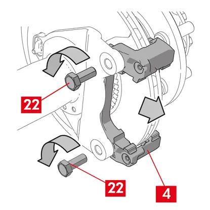
1. Poluzować śruby mocujące (punkt 22).
2. Zdjąć wspornik zacisku (punkt 4) ze wspornika piasty.
Procedura montażu
Zamontować nowe komponenty zapasowe.
1. Dokładnie wyczyścić wszystkie montowane komponenty (nowe i te wymontowane wcześniej), gniazda tulei i gniazda sprężyn za pomocą odpowiednich produktów (np. wilgotnej ściereczki).
NIEBEZPIECZEŃSTWO! Sprawdzić, czy komponenty są nienaruszone, wymienić na nowe, jeżeli zostały uszkodzone.
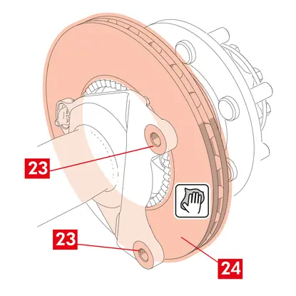
2. Wyczyścić powierzchnie montażowe (punkt 23) na wsporniku piasty.
3. Oczyścić powierzchnie hamujące (punkt 24) na tarczy za pomocą produktu do odtłuszczania (np. rozpuszczalnika SE47).
Montowanie wspornika zacisku
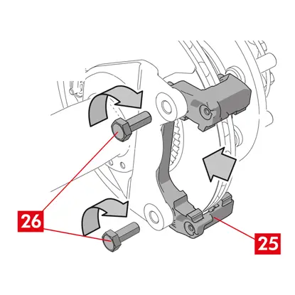
1. Umieścić nowy wspornik zacisku (punkt 25) na wsporniku piasty.
2. Włożyć i dokręcić śruby mocujące (punkt 26) momentem zalecanym przez producenta pojazdu.
Montowanie klocków i obudowy zacisku
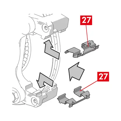
1. Włożyć na miejsca sprężyny (punkt 27), umieszczając je prawidłowo w obrębie gniazd.
2. W przypadku zacisku typu ECS52 z czterema sprężynami należy zawsze zakładać sprężyny tak, aby wypustki (punkt 28) były skierowane na zewnątrz wspornika zacisku.
OSTRZEŻENIE! Jeżeli dostępne są klocki ze stroną przylepną, należy zamontować nowe klocki; postępować według instrukcji dostarczonych z nowymi klockami.
PRZESTROGA! Klocek ze wskaźnikiem zużycia musi zostać umieszczony w pierwotnym położeniu, w jakim znajdował się, zanim został wymontowany..
NIEBEZPIECZEŃSTWO! Włożyć klocki tak, aby materiał cierny był skierowany w stronę tarczy.
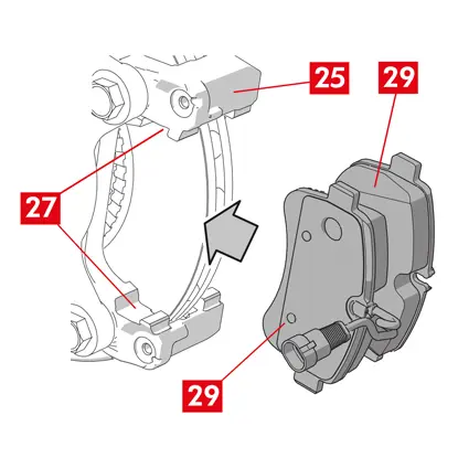
3. Włożyć klocki (punkt 29) do wspornika zacisku (punkt 25); użyć śrubokręta, aby podważyć sprężyny boczne (punkt 27).
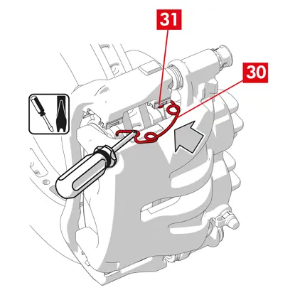
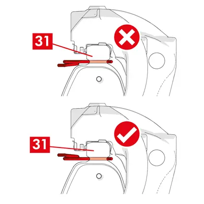
4. W przypadku sprężyn ograniczających moment resztkowy (punkt 30) należy zaczepić sprężynę pod płytką (punkt 31) i zaczepić spodnią część płytki na drugim klocku za pomocą śrubokręta typu U.
NIEBEZPIECZEŃSTWO! Nieprawidłowe przymocowanie sprężyny może spowodować jej gwałtowne otwarcie się.
NIEBEZPIECZEŃSTWO! Nieprawidłowe przymocowanie sprężyny może spowodować jej gwałtowne otwarcie się.
PRZESTROGA! Zamontować we właściwym kierunku.
PRZESTROGA! Jeżeli obudowa zacisku jest nowa, nie należy wyjmować osłony zabezpieczającej z otworu wlotowego płynu na nowym zacisku do momentu przyłączenia do niego przewodu doprowadzającego.
6. Ustawić obudowę zacisku (punkt 32), wkładając ją do tarczy tak, aby tuleje prowadzące były dopasowane do otworów na wsporniku zacisku.
PRZESTROGA! Uważać, aby nie uszkodzić pokryw.
7. Wepchnąć tuleje prowadzące (punkt 33) do gniazd na wsporniku zacisku.
8. Włożyć i dokręcić śruby (punkt 34) momentem 32 – 36 Nm.
9. Ustawić osłony (punkt 35).
PRZESTROGA! Przed zdjęciem osłony zabezpieczającej należy ustawić punkt doprowadzania możliwie jak najwyżej, upewniając się, że nie wycieknie płyn hamulcowy znajdujący się wewnątrz zacisku.
10. Podłączyć z powrotem przewód wskaźnika zużycia, jeżeli występuje, do końcówki w pojeździe, i lekko naciskając przymocować do podkładki na zacisku, jeżeli występuje, oraz do wszelkich mocowań w podwoziu.
Podłączanie przewodu doprowadzającego płyn hamulcowy
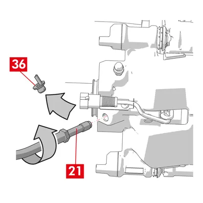
1. Zdjąć osłonę zabezpieczającą (punkt 36) z otworu wlotowego płynu hamulcowego.
2. Podłączyć przewód doprowadzający płyn hamulcowy (punkt 21).
3. Wyjąć rozpórkę umieszczoną wcześniej we wnętrzu pojazdu, co spowoduje zwolnienie pedału hamulca i ponowne otwarcie obwodu.
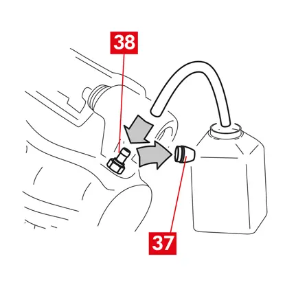
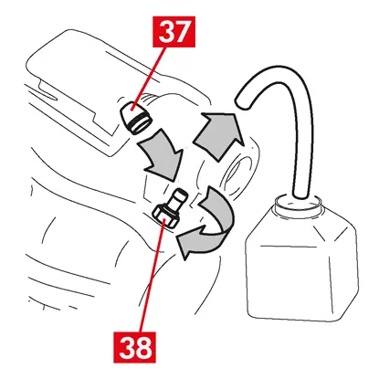
4. Zdjąć osłonę zabezpieczającą (punkt 37) z korka odpowietrznika (punkt 38).
5. Podłączyć przeźroczysty przewód do korka odpowietrznika (punkt 38) na zacisku, a drugi koniec włożyć do pojemnika, aby zebrać płyn.
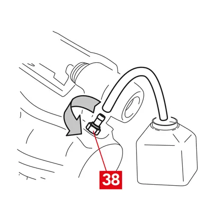
6. Otworzyć korek odpowietrznika (punkt 38).
7. Nacisnąć kilkukrotnie pedał hamulca, aż płyn hamulcowy zacznie wypływać z korka odpowietrznika.
8. Trzymając pedał w pozycji wciśniętej, zamknąć korek odpowietrznika. Zwolnić pedał, poczekać kilka sekund, a następnie powtórzyć procedurę, aż wypływający płyn nie będzie miał żadnych pęcherzyków powietrza i zostanie przywrócony normalny opór oraz zakres ruchu pedału hamulca.
9. Dokręcić korek odpowietrznika (punkt 38) momentem podanym w poniższej tabeli:
| Typ odpowietrznika | M10x1 |
| Moment dokręcenia | 12÷16 Nm |
10. Wyjąć przezroczysty wężyk.
11. Powtórzyć procedurę odpowietrzania dla pozostałych korków odpowietrznika.
12. Założyć na miejsce osłonę zabezpieczającą (punkt 37).
13. Po zakończeniu procedury odpowietrzania całkowicie cofnąć tłoczki w zacisku, używając odpowiedniego narzędzia (na przykład ściągacza) i uzupełnić płyn, zgodnie z zaleceniami producenta.
14. Przy uruchomionym silniku wcisnąć mocno pedał hamulca i sprawdzić, czy nie występują wycieki płynu z zacisku lub nieprawidłowy spadek ciśnienia w obwodzie, a tylne światła stop włączają się.
NIEBEZPIECZEŃSTWO! Jeżeli płyn wycieka z zacisku, należy powtórzyć wszystkie czynności podane w tym dokumencie, aby określić przyczynę problemu i rozwiązać go.
Montowanie modułu urządzenia uruchamiającego
OSTRZEŻENIE! Moduł urządzenia uruchamiającego może zostać dostarczony w postaci już zamontowanej w obudowie zacisku.
Zamontować nowe komponenty zapasowe.
- Wyczyścić wszelkie wymontowane wcześniej komponenty przed zamontowaniem ich na miejscu.
PRZESTROGA! Zawsze używać nowych śrub posmarowanych klejem do śrub. Zawsze zakładać nową uszczelkę.
NIEBEZPIECZEŃSTWO! Sprawdzić, czy komponenty są nienaruszone, wymienić na nowe, jeżeli zostały uszkodzone.
1. Oczyścić powierzchnię styku na zacisku i na module urządzenia uruchamiającego.
2. Usunąć resztki kleju do śrub z gniazd śrub gwintowanych.
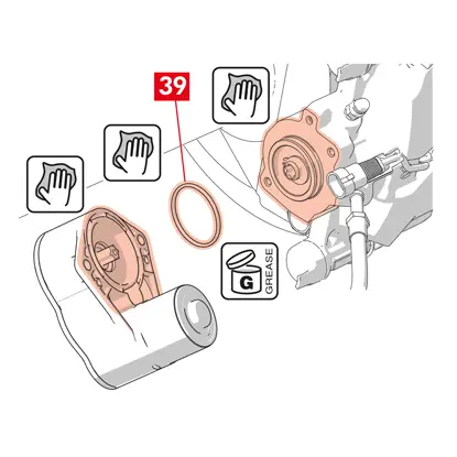
3. Oczyścić i nasmarować uszczelkę (punkt 39) dostarczonym smarem.
4. Nasmarować złącze modułu urządzenia uruchamiającego na całej średnicy wewnętrznej dostarczonym smarem.
OSTRZEŻENIE! EUH210 — karta charakterystyki dostępna na życzenie.
OSTRZEŻENIE! EUH208 — zawiera N-alkilowany benzotriazol. Może wywołać reakcję alergiczną.
5. Włożyć uszczelkę (punkt 39) do gniazda (punkt 40) na obudowie zacisku.
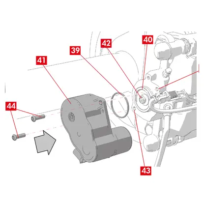
6. Założyć moduł urządzenia uruchamiającego (punkt 41) na śrubę typu torx (punkt 42) na obudowie zacisku.
7. Obrócić moduł urządzenia uruchamiającego (punkt 41) tak, aby otwory (punkt 43) śrub mocujących (punkt 44) były dopasowane do pierwotnego położenia montażowego.
PRZESTROGA! Uważać, aby nie uszkodzić uszczelki (punkt 39) podczas montowania modułu urządzenia uruchamiającego w obudowie zacisku.
8. Włożyć i dokręcić śruby mocujące (punkt 44) momentem 7 – 10 Nm.

9. Zdjąć osłonę zabezpieczającą (punkt 45), jeżeli występuje, i podłączyć kabel elektryczny (punkt 6).
10. Jeżeli wcześniej wymontowano, przykręcić dławik (punkt 5).
11. Zamocować kabel zasilający modułu urządzenia uruchamiającego (punkt 6) do dławika (punkt 5).
Ostatnie etapy
1. Założyć koło.
2. Wykonać procedurę resetowania (sprawdzenie montażu).
3. W razie potrzeby zresetować liczniki (Reset Internal Counters) zgodnie z instrukcjami producenta pojazdu.
4. Jeżeli wymaga tego producent pojazdu, klocki należy dotrzeć.
5. Odłączyć przyrząd diagnostyczny. (diagnostyka pojazdu — OBD).
W tym miejscu zamieszczono instrukcje wymiany obudowy zacisków pływających z 2 lub 4 sprężynami bocznymi i sprężynami ograniczającymi moment resztkowy.
W przypadku wymiany samych śrub mocujących należy się zapoznać tylko z odpowiednimi sekcjami.
Procedura wymiany
Przed rozpoczęciem wymiany upewnić się, że używane części zamienne są odpowiednie dla danej marki i danego modelu pojazdu.
- Zanotować położenie wszystkich częściowo lub całkowicie wymontowanych komponentów, aby umożliwić późniejsze prawidłowe zamontowanie ich na miejscu.
- Zdjąć koło.
Dotyczy zacisków ECS
OSTRZEŻENIE! W przypadku usterki elektrycznej wymontować moduł urządzenia uruchamiającego (punkt 5) i wycofać tłoczek, obracając śrubę typu torx w kierunku zgodnym z ruchem wskazówek zegara, posługując się odpowiednim kluczem płaskim.
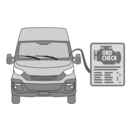
1. Podłączyć do pojazdu przyrząd diagnostyczny (diagnostyka pojazdu — OBD) i przejść do trybu serwisowego zgodnie z opisem producenta pojazdu.
PRZESTROGA! Bez wykonania tej czynności nie można cofnąć tłoczka za pomocą ściągacza lub innego odpowiedniego narzędzia.
PRZESTROGA! Upewnić się, że część zamienna jest zgodna z oprogramowaniem pojazdu.
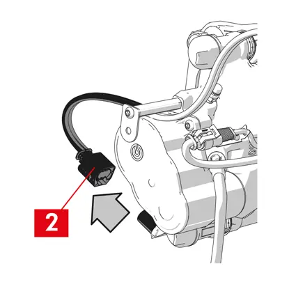
2. Odłączyć kabel zasilania (punkt 2) od modułu urządzenia uruchamiającego.
OSTRZEŻENIE! Złącze można zamocować za pomocą zatrzasku zabezpieczającego.
Dotyczy wszystkich typów zacisków
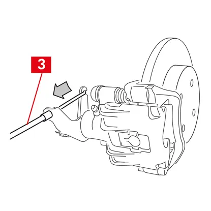
1. W przypadku zacisków z hamulcem postojowym odłączyć od zacisku linkę sterującą (punkt 3).
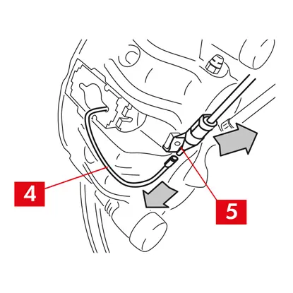
2. Odłączyć wskaźnik zużycia (punkt 4), jeżeli występuje, od końcówki w pojeździe, wyjmując go z podkładki (punkt 5) mocującej do zacisku oraz z wszelkich mocowań na podwoziu.
3. Zdjąć osłony zabezpieczające (punkt 6) z tulei prowadzących.
4. Jeżeli osłona posiada wystającą krawędź (punkt 7), należy ściągnąć ją (punkt 7) palcami.
5. Jeżeli osłona jest wykonana z twardego tworzywa sztucznego (punkt 8), należy podważyć ją śrubokrętem. Wyjęcie osłony w taki sposób spowoduje jej pęknięcie.
OSTRZEŻENIE! Nie używać ponownie wymontowanej osłony z tworzyw sztucznych.
PRZESTROGA! Tuleja prowadząca, którą zamierza się wymontować, musi umożliwiać obrócenie obudowy zacisku bez naprężania przewodu doprowadzającego płyn.
OSTRZEŻENIE! Dostępne są dwa typy tulei prowadzących: z osobną śrubą, ze zintegrowaną śrubą.
6. Poluzować i całkowicie wykręcić śrubę (punkt 9) lub zintegrowaną tuleję prowadzącą (punkt 10) kluczem płaskim.

7. W przypadku tulei prowadzącej bez zintegrowanej śruby (punkt 11) wyciągnąć tuleję prowadzącą ze wspornika zacisku (punkt 12), podważając ją w gnieździe śrubokrętem.
8. W przypadku wymiany zacisku na kołach tylnych z zawieszeniem i resorami piórowymi należy zdjąć dwie tuleje prowadzące (punkt 11), aby całkowicie oddzielić obudowę zacisku (punkt 13) od wspornika zacisku (punkt 12).
OSTRZEŻENIE! Jeżeli do zacisku przyklejone są klocki, należy je rozdzielić za pomocą śrubokręta i uważać, aby nie uszkodzić części gumowych zacisku.
NIEBEZPIECZEŃSTWO! Otwarcie obudowy zacisku może spowodować gwałtowne otwarcie sprężyn ograniczających moment resztkowy.
9. Odsunąć obudowę zacisku (punkt 13) od wspornika zacisku (punkt 12), obracając ją wokół drugiej tulei prowadzącej, aż klocki (punkt 14) wyjdą ze wspornika zacisku. Przymocować obudowę zacisku do podwozia pojazdu za pomocą odpowiednich podpór. Nie używać gniazda tulei jako punktu mocowania.
11. Wyjąć klocki (punkt 14), nie uszkadzając ich.
12. Za pomocą pisaka oznaczyć kierunek obrotu tarczy na klockach, aby uniknąć ich nieprawidłowego zamontowania.
14. Jeżeli nadal są na swoim miejscu, należy wyjąć sprężyny ograniczające moment resztkowy (punkt 15).
15. We wnętrzu pojazdu umieścić między siedzeniem a pedałem hamulca rozpórkę (punkt 16), aby pedał pozostał wciśnięty podczas wykonywania tych czynności.
OSTRZEŻENIE! Umożliwia to zamknięcie obwodu płynu hydraulicznego i uniknięcie wycieku płynu hamulcowego.
PRZESTROGA! Na każdym opisanym poniżej etapie upewnić się, że płyn hamulcowy nie ma kontaktu z częściami pojazdu, które mogą zostać uszkodzone, szczególnie z elementami lakierowanymi. Natychmiast zetrzeć rozlany płyn hamulcowy ręcznikiem papierowym i wymyć powierzchnię wodą.
PRZESTROGA! Na każdym opisanym poniżej etapie upewnić się, że płyn hamulcowy nie ma kontaktu z częściami pojazdu, które mogą zostać uszkodzone, szczególnie z elementami lakierowanymi. Natychmiast zetrzeć rozlany płyn hamulcowy ręcznikiem papierowym i wymyć powierzchnię wodą.
16. Poluzować przewód doprowadzający (punkt 17) na zacisku na tyle, aby móc odkręcić go całkowicie ręką, ponieważ zapobiegnie to wyciekaniu płynu hamulcowego.
17. Poluzować całkowicie i wykręcić śrubę (punkt 9) lub zintegrowaną tuleję prowadzącą (punkt 10).
18. W przypadku tulei prowadzącej bez zintegrowanej śruby (punkt 11) wyciągnąć tuleję prowadzącą ze wspornika zacisku (punkt 12), podważając ją w gnieździe śrubokrętem.
19. Wyciągnąć obudowę zacisku (punkt 13) ze wspornika zacisku (punkt 12), uważając, aby nie naprężyć przewodu doprowadzającego płyn hamulcowy.
20. Całkowicie odłączyć przewód doprowadzający (punkt 17) od obudowy zacisku.
21. Jak najszybciej zetrzeć rozlany płyn hamulcowy.
22. Ustawić przewód doprowadzający w pozycji podniesionej, aby zapobiec wyciekom płynu hamulcowego.
23. Odsunąć zacisk do wymiany.
24. W przypadku zacisków z wbudowanym hamulcem postojowym odłączyć przewód hamulca postojowego od gniazda w zacisku.
25. Oczyścić powierzchnie hamujące na tarczy za pomocą produktu do odtłuszczania (np. rozpuszczalnika SE47).
Montowanie klocków
PRZESTROGA! Jeżeli dostępne są klocki ze stroną przylepną, należy zamontować nowe klocki; postępować według instrukcji dostarczonych z nowymi klockami.
1.Sprawdzić, czy sprężyny zostały prawidłowo ustawione. W przypadku zacisków z czterema sprężynami upewnić się, że wypustki są zawsze skierowane na zewnątrz wspornika zacisku.
PRZESTROGA! Nieprawidłowe ustawienie sprężyn może spowodować obrażenia ciała.

2. Włożyć klocki (punkt 14) do wspornika zacisku (punkt 12). Użyć śrubokręta w celu ściśnięcia sprężyn bocznych.
OSTRZEŻENIE! Strzałki umieszczone na klockach muszą być skierowane w kierunku obrotu tarczy.
NIEBEZPIECZEŃSTWO! Włożyć klocki tak, aby materiał cierny był skierowany w stronę tarczy.
PRZESTROGA! Klocek ze wskaźnikiem zużycia musi zostać umieszczony w pierwotnym położeniu, w jakim znajdował się, zanim został wymontowany..
3. Jeżeli występuje, należy podłączyć końcówkę wskaźnika zużycia (punkt 20) do klocka naprzeciwko tłoczków; wymienić je w razie potrzeby.
PRZESTROGA! Podczas podłączania końcówki wskaźnika zużycia należy się upewnić, że najbardziej wystająca część jest skierowana w stronę powierzchni ciernej klocka.
PRZESTROGA! Podczas podłączania końcówki wskaźnika zużycia należy się upewnić, że najbardziej wystająca część jest skierowana w stronę powierzchni ciernej klocka.
Montowanie obudowy zacisku
PRZESTROGA! W przypadku zacisków z hamulcem postojowym, gdy obudowa zacisku jest wymontowana z tarczy hamulcowej i/lub nie ma klocków hamulcowych, nie należy przesuwać tłoczka hydraulicznie ani za pomocą dźwigni, ponieważ może to spowodować uszkodzenie sprężyny i/lub wyciek płynu hamulcowego.
1. Wytrzeć wilgotną ściereczką na wsporniku zacisku powierzchnie przylegające (punkt 21) do obudowy zacisku (gniazda prowadzące).
PRZESTROGA! Nie używać produktów, które mogą uszkodzić pokrywy zabezpieczające, takich jak rozcieńczalnik na bazie nitro-czterochloroetylenu, benzyna itp.
2. Oczyścić i równomiernie nasmarować całą powierzchnię wewnętrzną pokryw, powierzchnię zewnętrzną tulei prowadzących i ich gniazda w obudowie zacisku.
3. Ustawić nową obudowę zacisku (punkt 22), wkładając jedną z dwóch tulei prowadzących (punkt 10) do gniazda na wsporniku zacisku (punkt 12).
PRZESTROGA! Nie zdejmować osłony zabezpieczającej z otworu wlotowego płynu hamulcowego, aż do ostatecznego podłączenia przewodu.
PRZESTROGA! Nie zdejmować osłony zabezpieczającej z otworu wlotowego płynu hamulcowego, aż do ostatecznego podłączenia przewodu.
4. W przypadku niezintegrowanej tulei prowadzącej (punkt 11) włożyć i dokręcić nową śrubę (punkt 23).
5. Ostrożnie zamknąć zacisk, obracając jego obudowę (punkt 22) wokół osadzonej tulei prowadzącej.
PRZESTROGA! Ostrożnie zamknąć zacisk i sprawdzić, czy pokrywy zabezpieczające na tulejach nie zostały uszkodzone, stukając o wspornik zacisku. W razie potrzeby wymienić pokrywy.
OSTRZEŻENIE! Jeżeli dostępne są klocki ze stroną przylepną, należy uważać, aby nie zetknąć obudowy i klocka przed zamontowaniem obudowy zacisku.
6. Przeprowadzić sondę wskaźnika zużycia (punkt 20) przez odpowiedni otwór w obudowie zacisku (punkt 22).

7. Włożyć drugą tuleję prowadzącą (punkt 10) do gniazda wspornika zacisku (punkt 12).
8. W przypadku niezintegrowanej tulei prowadzącej (punkt 11) włożyć i dokręcić nową śrubę (punkt 24).
PRZESTROGA! W przypadku wymiany wspornika zacisku na tylnych kołach z zawieszeniem i resorami piórowymi należy umieścić obudowę zacisku na wsporniku zacisku, a następnie włożyć obie tuleje prowadzące oraz włożyć i dokręcić dwie nowe śruby.
9. Dokręcić śrubę mocującą tulei prowadzącej lub wbudowaną tuleję prowadzącą (punkt 24) po stronie wejściowej tarczy (po wybraniu biegu jazdy do przodu). Następnie dokręcić drugą śrubę lub wbudowaną tuleję prowadzącą (punkt 25) takim samym momentem.
10. Dokręcić momentem podanym w poniższej tabeli:
| Typ | Moment dokręcenia | |
| Śruba mocująca | (M8 – CH6) | 32 ÷ 36 Nm |
| Tuleja prowadząca ze zintegrowaną śrubą | (M8 – CH6) | 32 ÷ 36 Nm |
| Tuleja prowadząca ze zintegrowaną śrubą | (M10 – CH8) | 65 ÷ 75 Nm |
NIEBEZPIECZEŃSTWO! Dokręcać według podanej kolejności; nieprzestrzeganie tej instrukcji może uniemożliwić prawidłowe działanie zacisku.
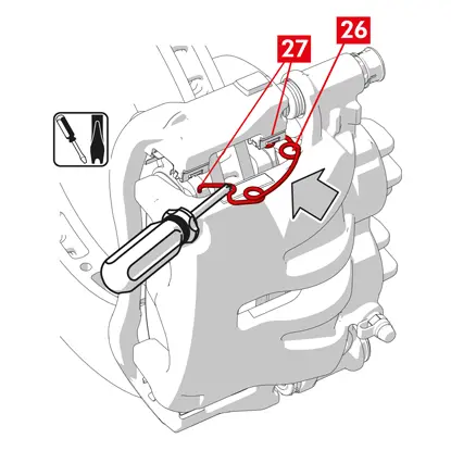
11. W przypadku sprężyn ograniczających moment resztkowy (punkt 26) należy zaczepić sprężynę pod płytką (punkt 27) i zaczepić spodnią część płytki na drugim klocku za pomocą śrubokręta typu U.
NIEBEZPIECZEŃSTWO! Nieprawidłowe przymocowanie sprężyny może spowodować jej gwałtowne otwarcie się.
PRZESTROGA! Zamontować we właściwym kierunku.
12. Ostrożnie oczyścić część (punkt 28), aby upewnić się, że pozostanie na miejscu i założyć nowe osłony zabezpieczające (punkt 29), nasmarować ich powierzchnię wewnętrzną oraz gniazdo obudowy zacisku smarem dostarczonym w zestawie części zapasowych.
OSTRZEŻENIE! EUH210 — karta charakterystyki dostępna na życzenie.
OSTRZEŻENIE! EUH208 — zawiera N-alkilowany benzotriazol. Może wywołać reakcję alergiczną.
OSTRZEŻENIE! EUH208 — zawiera N-alkilowany benzotriazol. Może wywołać reakcję alergiczną.
13. Obrócić osłony zabezpieczające (punkt 29) tak, aby całkowicie przylegały do gniazda (punkt 30).
14. Podłączyć z powrotem wskaźnik zużycia, jeżeli występuje, do końcówki w pojeździe, i lekko naciskając przymocować do podkładki na zacisku oraz do wszelkich mocowań w podwoziu.
15. Zdjąć osłonę zabezpieczającą z otworu wlotowego płynu hamulcowego.
16. Podłączyć z powrotem przewód doprowadzający płyn hamulcowy.
17. Wyjąć rozpórkę umieszczoną wcześniej we wnętrzu pojazdu, co spowoduje zwolnienie pedału hamulca i ponowne otwarcie obwodu.
Dotyczy zacisków z hamulcem postojowym
PRZESTROGA! Przed zmontowaniem tłoczka z klockami należy się upewnić, że zamontowano wspornik zacisku, klocki i tarczę.
- Użyć dźwigni, aby zmontować tłoczek z klockami.
PRZESTROGA! Użycie narzędzia hydraulicznego jest dozwolone tylko wtedy, gdy tłoczek znajduje się w odległości mniejszej niż 1 mm od klocków.
Dotyczy wszystkich typów zacisków
1. Podłączyć przeźroczysty wężyk do korka odpowietrznika (punkt 31) na zacisku, a drugi koniec włożyć do pojemnika, aby zebrać płyn.
2. Otworzyć korek odpowietrznika (punkt 31).
3. Nacisnąć kilkukrotnie pedał hamulca, aż płyn hamulcowy zacznie wypływać z korka odpowietrznika.
4. Trzymając pedał w pozycji wciśniętej, zamknąć korek odpowietrznika. Zwolnić pedał, poczekać kilka sekund, a następnie powtórzyć procedurę, aż wypływający płyn nie będzie miał żadnych pęcherzyków powietrza i zostanie przywrócony normalny opór oraz zakres ruchu pedału hamulca.
5. Dokręcić korek odpowietrznika (punkt 31) momentem podanym w tabeli:
| Korek odpowietrznika | M6x1 | M8x1,25 | M10x1 | M12x1 |
| Moment dokręcenia | 5÷7 Nm | 7÷10 Nm | 17÷20 Nm | 18÷22 Nm |
6. Wyjąć przezroczysty wężyk.
7. Powtórzyć procedurę odpowietrzania dla pozostałych korków odpowietrznika.
8. Po zakończeniu procedury odpowietrzania całkowicie cofnąć tłoczki w zacisku, używając odpowiedniego narzędzia (na przykład ściągacza) i uzupełnić płyn, zgodnie z zaleceniami producenta.
9. Zakręcić korek zbiornika płynu hamulcowego.
10. Przy uruchomionym silniku wcisnąć mocno pedał hamulca i sprawdzić, czy nie występują wycieki płynu z zacisku lub nieprawidłowy spadek ciśnienia w obwodzie, a tylne światła stop włączają się.
NIEBEZPIECZEŃSTWO! Jeżeli płyn wycieka z zacisku, należy powtórzyć wszystkie czynności podane w tym dokumencie, aby określić przyczynę problemu i rozwiązać go.
Dotyczy zacisków z hamulcem postojowym
- Podłączyć z powrotem wskaźnik zużycia, jeżeli występuje, do końcówki w pojeździe, i lekko naciskając przymocować do podkładki na zacisku oraz do wszelkich mocowań w podwoziu.
- Przywrócić prawidłowe naprężenie linki sterującej.
- Kilkakrotnie użyć dźwigni hamulca postojowego w pojeździe, aż do uzyskania standardowego skoku.
Dotyczy zacisków ECS
1. Zdjąć osłonę zabezpieczającą (jeżeli występuje) i podłączyć kabel zasilania elektrycznego (punkt 2).
2. Wykonać procedurę resetowania (sprawdzenie montażu).
3. W razie potrzeby zresetować liczniki (Reset Internal Counters) zgodnie z instrukcjami producenta pojazdu.

4. Jeżeli wymaga tego producent pojazdu, klocki należy dotrzeć.
5. Odłączyć przyrząd diagnostyczny (diagnostyka pojazdu — OBD).
Dotyczy wszystkich typów zacisków
1. Założyć koło.
2. Jeżeli klocki są nowe, wymagają dotarcia; należy postępować wg instrukcji dostarczonych z klockami zamiennymi.
2. Jeżeli klocki są nowe, wymagają dotarcia; należy postępować wg instrukcji dostarczonych z klockami zamiennymi.
Ograniczenia gwarancji
Niniejsza gwarancja obejmuje wszystkie wady, które wystąpią w ciągu dwóch lat od momentu dostawy produktu. Zgłoszenie wady sprzedawcy przez konsumenta jest wymagane w ciągu dwóch miesięcy od jej stwierdzenia, bez wpływu na fakt, że okres ograniczeń dla podjęcia działania, którego celem jest usunięcie wady, wynosi dwadzieścia sześć miesięcy od momentu dostawy produktu. W przypadku wystąpienia wady użytkownik ma prawo do naprawy lub wymiany produktu, uzyskania odpowiedniego rabatu bądź zakończenia umowy, zgodnie z art. 130 Kodeksu konsumenckiego, w stosownych przypadkach.
Niniejsza gwarancja stanowi jedyną gwarancję udzielaną w związku z tym produktem i zastępuje wszelkie inne gwarancje, ustne oraz pisemne.
W przypadku wystąpienia wad od użytkownika wymaga się:
- pod karą unieważnienia gwarancji, aby powiadomił producenta i dystrybutora na piśmie w ciągu sześćdziesięciu dni; jednocześnie użytkownik powinien przekazać opis stwierdzonej wady produktu lub zwracanych części i dowód zakupu przez pierwotnego użytkownika zawierający nazwę produktu i datę zakupu (w ramach sprzedaży detalicznej lub za pośrednictwem dystrybutora w ramach instalacji produktu);
- wysłania produktu, w którym istnieje przypuszczenie wystąpienia wady do centrali firmy Brembo S.p.A. na adres Brembo 25, 24035 Curno (BG), Italy, poprzez łańcuch dystrybucji.
Gwarancja nie obowiązuje w przypadku:
- uszkodzenia produktu spowodowanego, częściowo lub całkowicie, nieprawidłową eksploatacją, wypadkiem, pożarem, korozją chemiczną, użytkowaniem niezgodnym z przeznaczeniem, użytkowaniem niedozwolonym, zastosowaniem w nieodpowiednim modelu, nieprawidłową instalacją, instalacją niezgodną z instrukcjami producenta lub brakiem konserwacji produktu zgodnie z informacjami producenta zamieszczonymi w dostarczonej instrukcji;
- reklamacji dotyczących komfortu, występowania szumów, drgań lub nieodpowiedniej charakterystyki prowadzenia pojazdu.
The Product has been designed and produced for the specific model and use indicated in the Brembo catalogues and/or by the Brembo product distributors, both available on the Brembo website (www.brembo.com). The Product shall be used according to the laws in force in the states and/or in the countries where the vehicle on which the Product is installed is used, including, but without limitation to, observance of the regulations of the Highway Code and after obtaining any authorisation/approval, permit or licence required by the state and/or country.
Produkt opracowano i wyprodukowano z myślą o konkretnym modelu i użytku określonym w katalogach Brembo i/lub przez dystrybutorów produktów Brembo. Informacje te są dostępne na stronie internetowej Brembo (www.brembo.com). Używać produktu zgodnie z przepisami obowiązującymi w regionach i/lub krajach, w których eksploatowany jest pojazd, w którym produkt jest zainstalowany i używany, a w szczególności zgodnie z przepisami ruchu drogowego oraz po uzyskaniu upoważnienia/homologacji, pozwolenia lub licencji wymaganej w danym regionie/kraju. W przypadku produktów sprzedawanych na terenie państw członkowskich Unii Europejskiej niniejsze ograniczenia gwarancji obowiązują zgodnie z przepisami dyrektywy 85/374/EOG Rady z 25 lipca 1985 roku.
W przypadku produktów sprzedawanych na terenie Stanów Zjednoczonych niniejsze ograniczenia gwarancji obowiązują zgodnie z określonymi przepisami federalnymi i stanowymi.
Informacje ogólne i dotyczące bezpieczeństwa
Ten produkt Brembo opracowano tak, aby spełniał wszelkie obowiązujące normy bezpieczeństwa. Produkty nie mogą być używane niezgodnie z przeznaczeniem, dla którego zostały opracowane i wyprodukowane. Użycie produktu w innym celu lub dowolna modyfikacja bądź naruszenie go może wpłynąć na jego działanie i spowodować, że stanie się on niebezpieczny.
Taka modyfikacja lub nieprawidłowa eksploatacja spowoduje unieważnienie ograniczonej gwarancji i może narazić osobę korzystającą w taki sposób z produktu na obrażenia ciała lub uszkodzenia mienia innych osób.
W niniejszych instrukcjach słowo ostrzegawcze „NIEBEZPIECZEŃSTWO!” oznacza procedury, których nieprzestrzeganie może z dużym prawdopodobieństwem spowodować poważne obrażenia ciała lub śmierć. Słowo „PRZESTROGA” oznacza procedury, których nieprzestrzeganie może spowodować uszkodzenia fizyczne, natomiast słowo „OSTRZEŻENIE!” oznacza procedury, których nieprzestrzeganie może spowodować uszkodzenie pojazdu.
NIEBEZPIECZEŃSTWO!
Przed rozpoczęciem wymiany należy się upewnić, że części zamienne są odpowiednie dla danej marki i danego modelu pojazdu. Ten produkt ma kluczowe znaczenie dla bezpiecznego działania pojazdu, w którym zamierza się go zainstalować i jest przeznaczony do instalacji tylko przez wykwalifikowaną osobę, która przeszła odpowiednie przeszkolenie i/lub posiada doświadczenie w zakresie jego instalacji oraz eksploatacji zgodnie z jego przeznaczeniem.
Osoba przeprowadzająca instalację musi korzystać z odpowiednich narzędzi zgodnie z posiadaną specjalizacją oraz dysponować wiedzą i doświadczeniem w zakresie napraw pojazdów. Nieprawidłowa instalacja spowodowana niedokładnym i niepełnym przestrzeganiem niniejszych instrukcji lub innymi działaniami spowoduje unieważnienie Ograniczonej gwarancji i może spowodować pociągnięcie osoby przeprowadzającej instalację do odpowiedzialności w przypadku obrażeń ciała lub uszkodzenia mienia.
Marka Brembo nie ponosi odpowiedzialności za żadne szkody ani obrażenia ciała spowodowane wobec osoby lub przez osobę korzystającą z pojazdu, w którym nieprawidłowo zainstalowano produkt zamienny.
Zużytego produktu zastępowanego przez ten produkt nie można instalować w innym pojeździe. Może to spowodować uszkodzenia mienia i obrażenia ciała, a nawet śmierć.
Należy zawsze sprawdzać, czy poziom w zbiorniku płynu hamulcowego mieści się między minimalnym i maksymalnym wskazaniem zamieszczonym na zbiorniku. Nieprawidłowy poziom może spowodować wycieki płynu hamulcowego lub zmniejszoną wydajność układu hamulcowego. Zbyt duża lub zbyt mała ilość płynu hamulcowego w zbiorniku może spowodować nieprawidłowe działanie hamulców, czego skutkiem mogą być obrażenia ciała, a nawet śmierć.
PRZESTROGA!
Części pozostałe po wymianie należy usuwać zgodnie z przepisami.
Nie wolno mocno uderzać ani uszkadzać produktu, jego części i komponentów, ponieważ może to negatywne wpłynąć na efektywność ich działania lub spowodować nieprawidłowe działanie. W razie potrzeby należy wymienić wszystkie uszkodzone części lub komponenty. Aby uniknąć obrażeń ciała, zalecamy podjęcie następujących działań:
- Używać odpowiedniego sprzętu, aby uniknąć wdychania pyłu powstałego podczas czyszczenia części.
- Zawsze nosić rękawice podczas demontażu i montażu komponentów z ostrymi krawędziami.
- Nie dopuszczać do kontaktu powierzchni skóry z materiałem ciernym klocków i szczęk hamulcowych, ponieważ może to spowodować otarcia.
- Nie wkładać rąk do gniazd klocków podczas wyjmowania tłoczków zacisków z wykorzystaniem sprężonego powietrza, ponieważ może to spowodować zmiażdżenie palców.
- Unikać bezpośredniego kontaktu z płynem hamulcowym, ponieważ może to spowodować podrażnienie skóry i oczu. Jeżeli dojdzie do przypadkowego kontaktu, należy dokładnie oczyścić dane miejsce zgodnie z instrukcjami producenta pojazdu lub płynu hamulcowego.
- Nie uderzać komponentów elektrycznych ani nie poddawać ich działaniu ładunków elektrostatycznych, ponieważ może to spowodować uszkodzenie elementów z tworzyw sztucznych.
- Chronić wymontowane komponenty elektryczne przed wilgocią.
- Sprawdzić prawidłowość połączenia styków elektrycznych oraz czy włączają się światła stop. Jeżeli nie, brak działania świateł stop może oznaczać obniżenie sprawności układu hamulcowego lub usterkę układu sygnalizacji hamowania.
- Nie dopuszczać do kontaktu środków smarnych z powierzchniami hamującymi tarczy hamulcowej, bębna, klocków i szczęk, ponieważ może to obniżyć efektywność działania układu hamulcowego i spowodować poważne uszkodzenia.
- Nie używać ostrych narzędzi do montowania elementów gumowych, ponieważ może to spowodować ich uszkodzenie. Sprawdzić, czy wszystkie uszkodzone części zostały wymienione.
Gwarancja
Ta gwarancja obejmuje niezgodności, które wystąpią w ciągu dwóch lat od momentu dostawy produktu. W przypadku wykrycia wady należy ją zgłosić w ciągu 60 dni od wykrycia oraz w ciągu dwóch lat od daty dokonania zakupu produktu. Jeżeli wada zostanie potwierdzona i jest objęta gwarancją, produkt zostanie naprawiony lub wymieniony na nowy bądź kompleksowo zregenerowany. Gwarancja nie obejmuje wad spowodowanych wyłącznie lub szczególnie w wyniku nieprawidłowego użytkowania produktu, wypadku, pożaru, korozji chemicznej lub nieprawidłowej instalacji.
Czy masz jakieś inne pytania?
Skontaktuj się z działem pomocy technicznej Brembo, nasi technicy odpowiedzą tak szybko, jak to możliwe!