


Instruktioner för byte av bromsok på personbilar och lätta nyttofordon
Läs och följ alla instruktioner noggrant. Du hittar samma instruktioner i bromsokets förpackning. Kom ihåg att behålla dem under hela produktens livscykel. Överlämna dem till den nya ägaren om du säljer ditt fordon.
Dessa monteringsanvisningar är en riktlinje för standard reparationsarbete och tar inte hänsyn till några speciella egenskaper som kan gälla för de olika bromssystemen. De särskilda anvisningarna från fordonets och bromssystemets tillverkare måste följas i detalj.
Detta dokument innehåller instruktioner för byte av bromsok:
1. Bromsok med en skiva
2. Fasta bromsok med dubbla skivor
3. Flytande bromsok med radialmonterade belägg, typ 2x60/68.
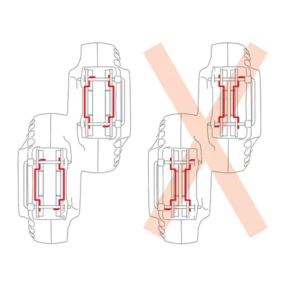
2. Fasta bromsok med dubbla skivor
3. Flytande bromsok med radialmonterade belägg, typ 2x60/68.
All information i detta instruktionsblad gäller för alla tre typerna av bromsok, om inget annat anges.
Förfarande för byte
Innan bytet påbörjas, kontrollera att reservdelarna som används för byte är lämpliga för fordonets märke och modell.
- Ta bort hjulet.
- Notera positionen för alla delvis eller helt demonterade komponenter för korrekt återmontering.
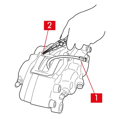
1. Koppla bort slitageindikatorkabeln (punkt 1), i förekommande fall, från uttaget i fordonet och lossa den från alla fästen på chassit och på bromsoket.
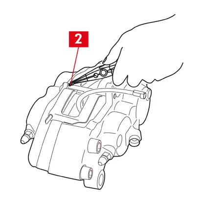
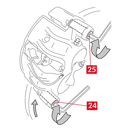
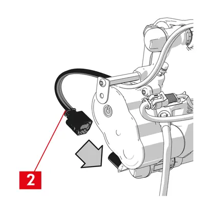
2. För modeller utrustade med säkerhetssprintar (punkt 2), ta bort dem med en tång.
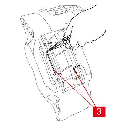
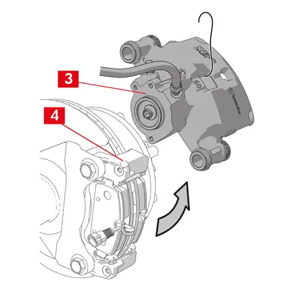
3. För bromsok med två skivor, ta bort fjädrarna (punkt 3) med hjälp av en tång.
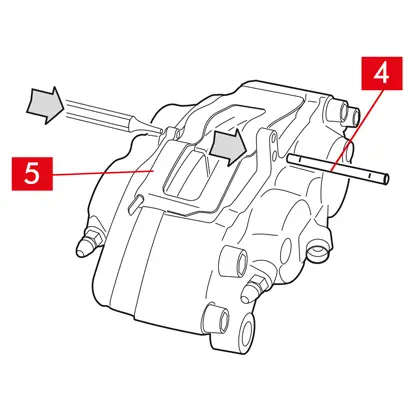
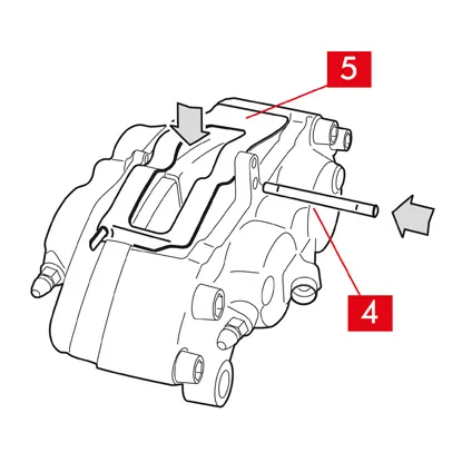
4. Dra ut stiftet/stiften (punkt 4) med hjälp av en hammare och en stiftmejsel. Dra ut helt för hand och se till att fjädrarna (punkt 5) hålls på plats.
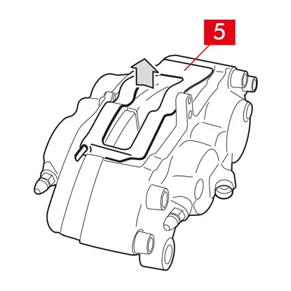
5. Ta bort fjädern/fjädrarna (punkt 5). Kontrollera vätskenivån. Öppna locket till bromsvätskebehållaren.
FÖRSIKTIGHET! Stegen för att dra tillbaka kolven som beskrivs nedan gör att bromsvätskenivån i behållaren stiger. Kontrollera att nivån på bromsvätskan inte orsakar läckage, eftersom detta kan skada fordonets lackerade delar.
FASTA BROMSOK typ A B
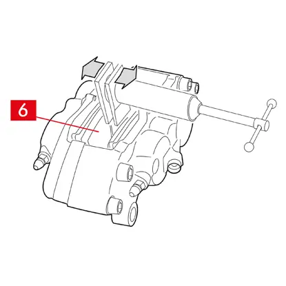
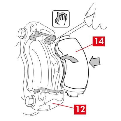
1. Dra ut kolvarna något med hjälp av en utdragsdon eller annat lämpligt verktyg och tryck på beläggen (punkt 6).
Kolven som dras tillbaka måste därefter göra det möjligt att lossa bromsoket från skivan.
2. Om bromsokets utformning tillåter det, ta bort beläggen. Ta annars bort dem efter demontering av bromsoket. Om du tänker återanvända beläggen, markera skivans rotationsriktning på dem med en penna.
FLYTANDE BROMSOK typ C
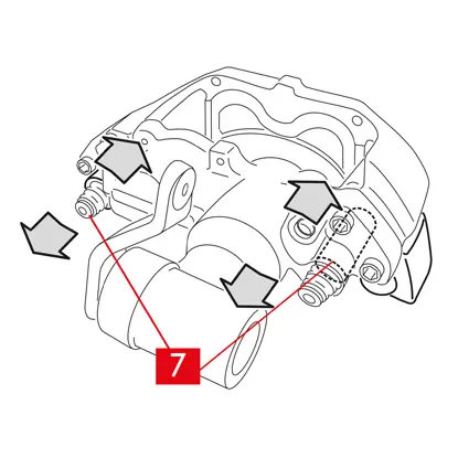
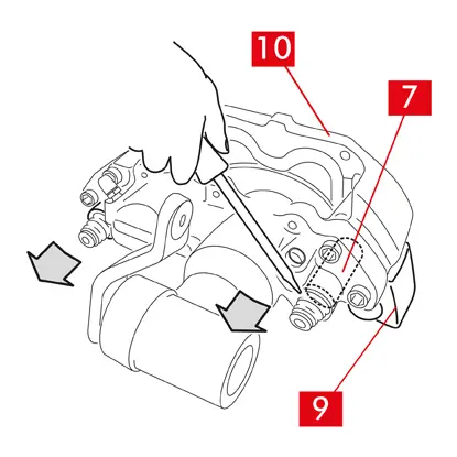
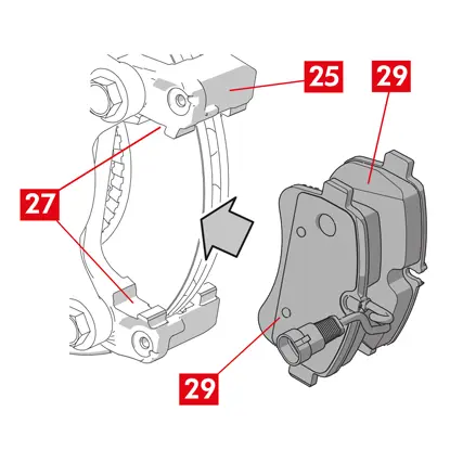
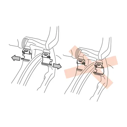
1. Ta ut beläggen samtidigt som du skjuter bromsokshuset fram och tillbaka på styrbussningarna (punkt 7). Genom att skjuta på bromsokshuset dras beläggen något bort från skivan, vilket gör det lättare att ta bort dem.
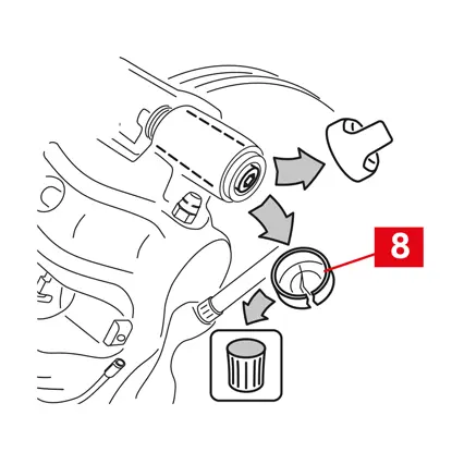
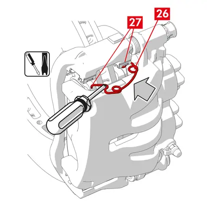
Om den fördjupning som uppstår vid skivslitage hindrar utdragningen av beläggen, demontera bromsokshuset:
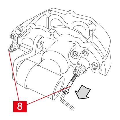
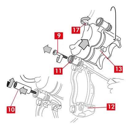
1. Demontera skruvarna (punkt 8) med hjälp av en skiftnyckel
2. Lyft ut styrbussningarna från de avsedda sätena med hjälp av en skruvmejsel.
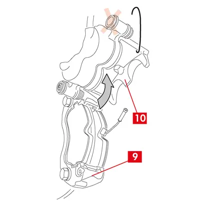
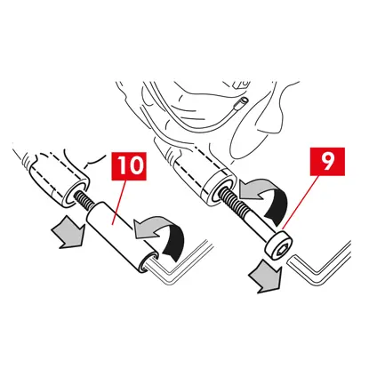
3. Ta ut styrbussningarna (punkt 7) så mycket att de lossnar från bromsokets fäste (punkt 9).
4. Lossa bromsokshuset (punkt 10) helt från bromsokets fäste (punkt 9) och häng upp det i fordonschassit med hjälp av en S-formad krok.
5. Ta ut beläggen.
6. Om du tänker återanvända beläggen, markera skivans rotationsriktning på dem med en penna.
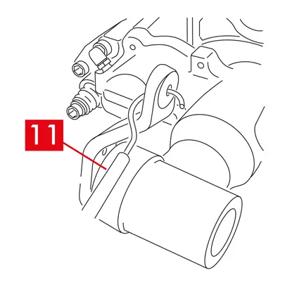
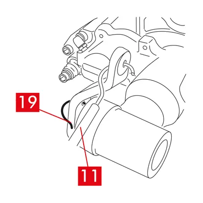
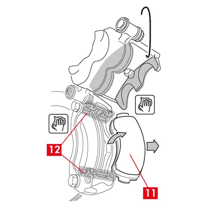
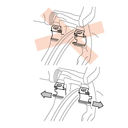
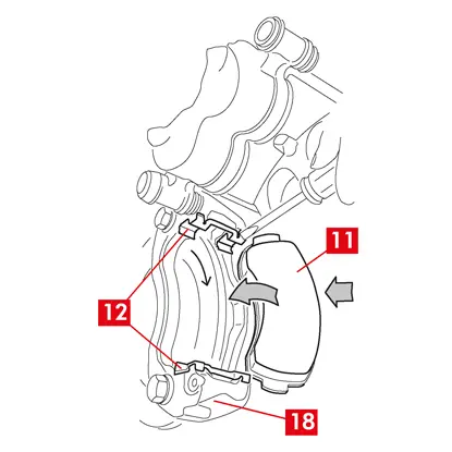
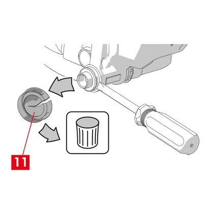
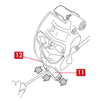
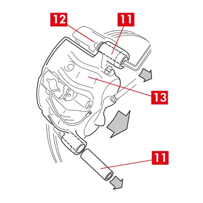
7. För bakre bromsok (med parkeringsmekanism), koppla loss parkeringskontrollkabeln (punkt 11).
FARA! Bromsvätskeledningarna måste vara lösa och får inte vara sträckta. Om du töjer slangarna kan de gå sönder och bromsvätska kan läcka ut.
För alla typer av bromsok
1. Stäng locket till bromsvätskebehållaren.
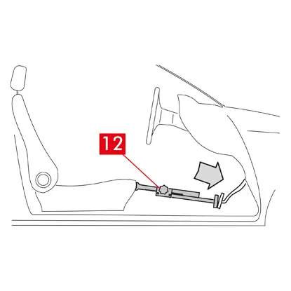
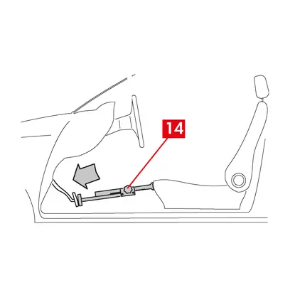
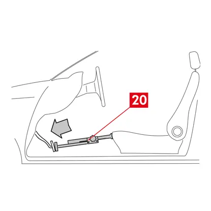
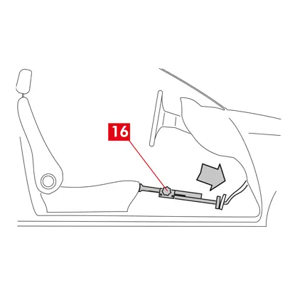
2. Placera en distans (punkt 12) i passagerarutrymmet mellan sätet och bromspedalen för att se till att pedalen förblir intryckt under hela tiden som dessa åtgärder pågår.
VARNING! Detta gör att bromsens hydraulkrets kan stängas, vilket förhindrar att bromsvätska läcker ut.
FÖRSIKTIGHET! Under alla faser som beskrivs nedan, se till att bromsvätskan inte kommer i kontakt med delar av fordonet som kan skadas, särskilt lackerade delar. Torka omedelbart av eventuella vätskestänk eller läckage med hushållspapper och rengör med vatten.
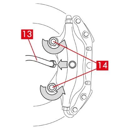
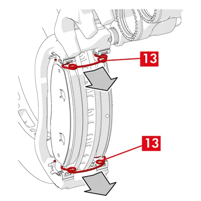
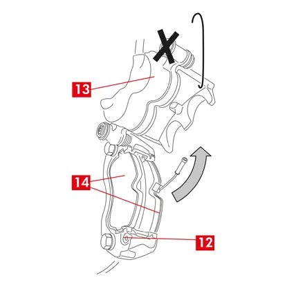
3. Lossa matningsledningen (punkt 13) på bromsoket så mycket att du kan skruva av den helt för hand, men undvik att bromsvätska läcker ut.
4. Skruva loss fästskruvarna (punkt 14) med en skiftnyckel och ta bort bromsoket från axeln.
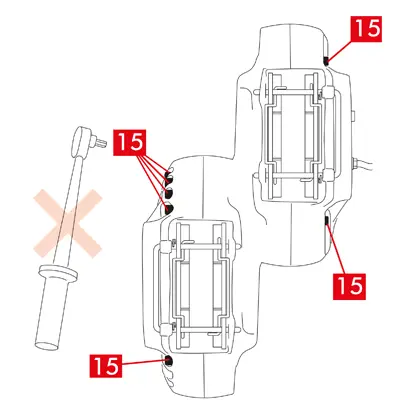
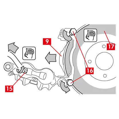
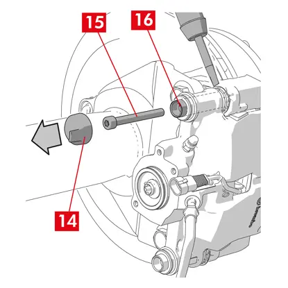
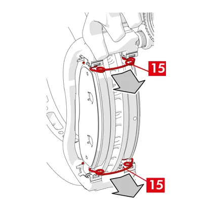
5. FÖRSIKTIGHET! För bromsok med dubbla skivor demonteras endast axelns fästskruvar. Demontera inte skruvarna (punkt 15) som håller ihop de halva bromsoken.
6. Lossa matningsledningen (punkt 13) helt från bromsoket.
7. Torka omedelbart bort eventuellt läckage av bromsvätska.
8. Håll matningsledningen upphöjd för att förhindra oavsiktliga vätskeläckage.
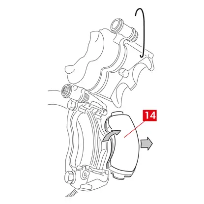
9. Dra bort det bromsok som ska bytas ut.
9. Dra bort det bromsok som ska bytas ut.
Monteringsprocedur
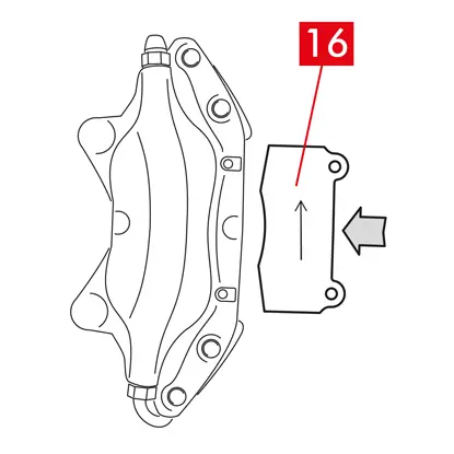
1. Sätt i beläggen (punkt 16) i det nya bromsoket.
VARNING! Eventuella pilar som är stämplade på beläggen måste peka i skivans rotationsriktning.
FARA! Belägg måste sättas in med friktionsmaterialet vänt mot skivan.
2. VARNING! Om bromsokets konstruktion tillåter det kan beläggen också sättas i efter att bromsoket har monterats, direkt efter steget "dra åt fästskruvarna".
FARA! Se till att friktionsytorna inte är nedsmutsade med fett, annars måste alla spår av fett avlägsnas med sandpapper.
3. Sätt tillbaka fjädrarna (punkt 5) och stiften (punkt 4) i de avsedda lägena i bromsoket och bromsbeläggen. Stiften måste föras in hela vägen med hjälp av en hammare och stiftdrivare.
Uppmärksamma riktningen vid montering av fjädrarna.
4. kontrollera att fjädrarna är korrekt placerade.
5. För modeller utrustade med säkerhetsstift (punkt 2), sätt tillbaka dem med hjälp av en tång.
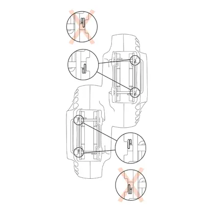
6. Kontrollera att stiften är korrekt placerade.
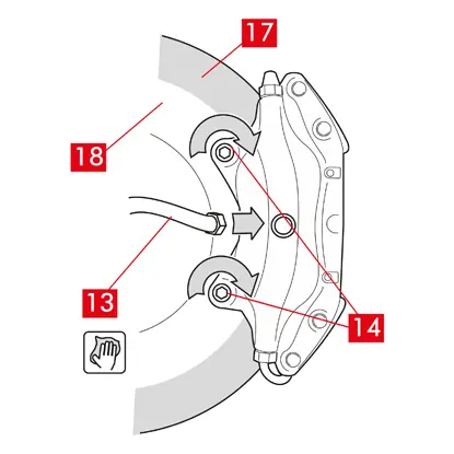
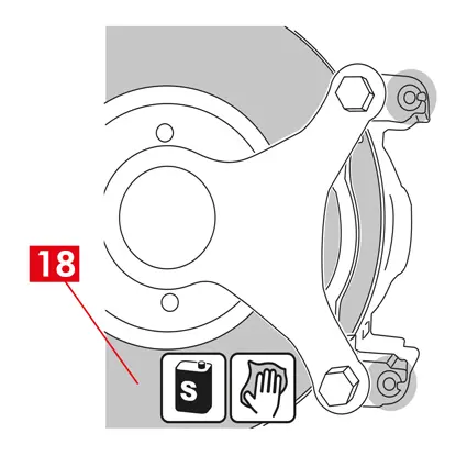
7. Rengör bromsytan (punkt 17) på skivan (punkt 18) med en avfettningsprodukt (t.ex. lösningsmedel SE 47).
8. Placera det nya bromsoket på axeln och för in skivan (punkt 18) mellan beläggen.
9. Dra åt fästskruvarna (punkt 14) med en skiftnyckel och använd det åtdragningsmoment som rekommenderas av fordonstillverkaren.
Alternativt kan följande rekommenderade åtdragningsmoment användas som referens:
| Typ av skruv | M12x1,25 | M12x1,5 | M14x1,5 |
| Åtdragningsmoment | 115 Nm | 125 Nm | 180 Nm |
10. Återanslut slitageindikatorns kabel, i förekommande fall, till uttaget i fordonet och till eventuella fästen på chassit och på bromsoket.
11. Koppla tillbaka bromsvätskeledningen (punkt 13).
12. Ta bort distansen som du tidigare placerade i passagerarutrymmet, vilket frigör pedalen från bromsen och gör att kretsen kan öppnas igen.
13. För bakre bromsok typ C (med parkeringsmekanism), återanslut parkeringskontrollkabeln (punkt 11).
14. Ta bort spakens låsstift (punkt 19).
15. Dra åt parkeringsbromsen inne i fordonet. Upprepa processen flera gånger tills bromsspakens slaglängd återgått till minimivärdena.
16. Öppna locket till bromsvätskebehållaren.
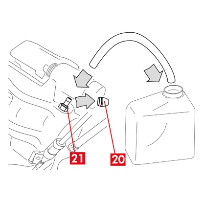
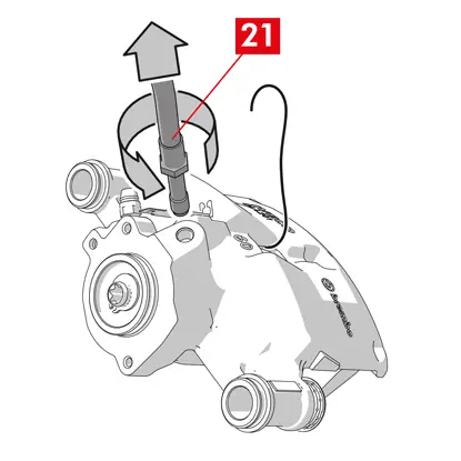
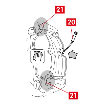
17. Ta bort skyddslocket (punkt 20) och anslut en genomskinlig slang till avtappningspluggen (punkt 21) på bromsoket, vars ändar ska placeras i en behållare för att samla upp eventuell vätska.
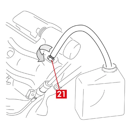
18. Öppna avtappningspluggen (punkt 21).
19. Tryck upprepade gånger på fordonets bromspedal tills bromsvätska börjar rinna ut ur avtappningspluggen.
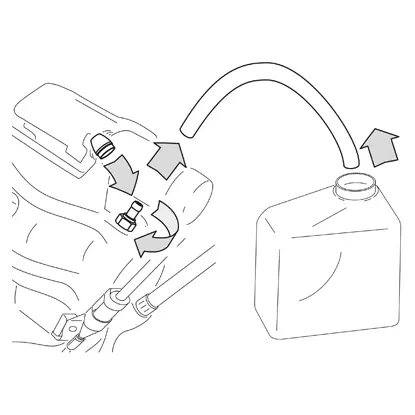
20. Håll ned pedalen och stäng avtappningspluggen. Släpp upp pedalen, vänta några sekunder och upprepa sedan processen tills vätska utan luftbubblor rinner ut och tills bromspedalens normala motstånd och rörelse återställs.
21. Dra åt avtappningspluggen med det åtdragningsmoment som anges i tabellen:
| Avtappningsplugg | M6x1 | M6x1 | M6x1 | M6x1 |
| Åtdragningsmoment | 5÷7 Nm | 7÷10 Nm | 17÷20 Nm | 18÷22 Nm |
22. Ta bort det genomskinliga röret och sätt tillbaka skyddskåpan på avtappningspluggen.
23. Upprepa avtappningsproceduren för alla andra avtappningspluggar.
24. Efter avtappningen drar du tillbaka kolvarna i bromsoket helt med hjälp av ett lämpligt verktyg (t.ex. en retraktor) och fyller sedan på vätskenivån enligt tillverkarens rekommendationer.
25. Stäng locket till bromsvätskebehållaren.
26. Med motorn igång, tryck hårt på fordonets bromspedal och kontrollera att det inte finns några vätskeläckage från bromsoket eller onormala tryckförluster i kretsen och att de bakre bromsljusen tänds.
FARA! Om vätska läcker från bromsoket, upprepa alla steg som beskrivs i detta dokument för att lokalisera orsaken och åtgärda problemet.
27. För bromsok med inbyggd parkeringsbroms, anslut parkeringsbromskabelns uttag till motsvarande fäste på bromsoket. Dra åt och lossa parkeringsbromsen upprepade gånger.
28. Sätt tillbaka hjulet.
29. Om beläggen är nya, kör in dem; följ instruktionerna som medföljer reservbeläggen
Nedan följer instruktioner för byte av bromsok:
Flytande bromsok med central fjäder
Flytande bromsok med 2 eller 4 sidofjädrar och fjädrar för reducering av resterande vridmoment.

All information i detta instruktionsblad gäller för alla typerna av bromsok, om inget annat anges.
Förfarande för byte
Innan bytet påbörjas, kontrollera att reservdelarna som används för byte är lämpliga för fordonets märke och modell.
- Ta bort hjulet
- Notera positionen för alla delvis eller helt demonterade komponenter för korrekt återmontering.
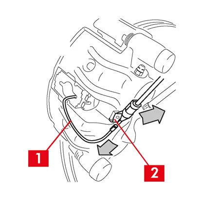
1. Koppla bort slitageindikatorn (punkt 1), i förekommande fall, från kontakten i fordonet, lossa den från mellanlägget (punkt 2) som håller fast den vid bromsoket och från alla fästen på chassit.
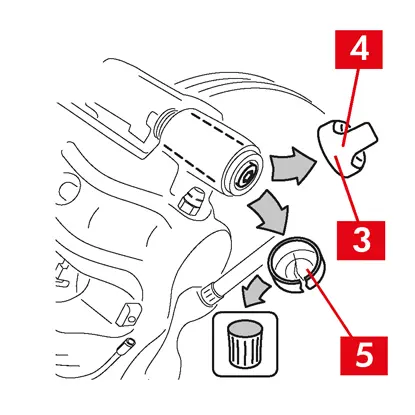
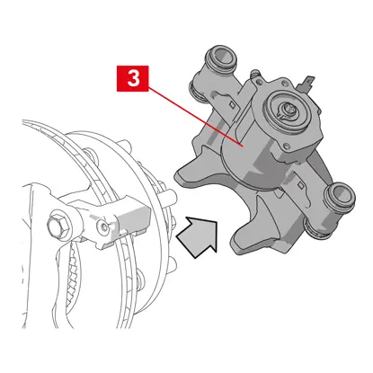
2. Ta bort skyddskåporna (punkt 3) från styrbussningarna.
3. Om locket har en förslutningsring (punkt 4), knäpp av locket genom att dra i förslutningsringen (punkt 4) med fingrarna.
4. Om locket är tillverkat av hårdplast (punkt 5), ta bort det med en skruvmejsel. Locket går sönder om det tas bort.
VARNING! Återanvänd inte det demonterade locket i hårdplast.
FÖRSIKTIGHET! Styrbussningen vid demontering måste vara den som gör att bromsokets kropp kan vridas utan att bromsvätskans matningsledning sträcks.
VARNING! Det finns två typer av vägledande bussar:
- med separat skruv
- med inbyggd skruv
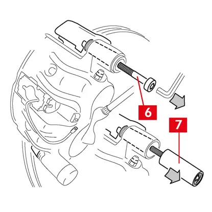
5. Lossa skruven (punkt 6) eller den inbyggda styrbussningen (punkt 7) med en skiftnyckel och ta bort den helt.
VARNING! Om bromsbelägg är fastlimmade på bromsoket, lossa dem med en skruvmejsel.
FARA! Om bromsoket öppnas kan fjädrarna som reducerar resterande vridmoment frigörs.
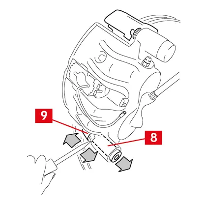
6. Om styrbussningen (punkt 8) inte är inkorporerad, dra ut styrbussningen ur bromsokets fäste (punkt 9) genom att trycka ut den ur sitt säte med en skruvmejsel.
7. Vid byte av bromsok på bakhjul med fjädring och bladfjädrar, måste båda styrbussningarna (punkt 8) tas bort för att separera bromsokets kropp (punkt 10) helt från bromsokets fäste (punkt 9).
8. Dra ut bromsoket (punkt 10) från bromsoksfästet (punkt 9) genom att vrida det runt den andra styrbussningen tills beläggen kommer ut ur bromsoksfästet. Fäst bromsoket på fordonschassit med hjälp av lämpliga stöd.
9. Ta bort dynorna (punkt 11) och fjädrarna (punkt 12) utan att skada dem så att du kan montera tillbaka dem på det nya bromsoket.
10. Markera skivans rotationsriktning på beläggen med en penna för att undvika felaktig återmontering.
11. Om de fortfarande är på plats, demontera fjädrarna för reducering av kvarvarande vridmoment (punkt 13).
12. Placera en distans (punkt 14) i passagerarutrymmet mellan sätet och bromspedalen för att se till att pedalen förblir intryckt under hela tiden som dessa åtgärder pågår.
VARNING! Detta gör att bromsens hydraulkrets kan stängas, vilket förhindrar att bromsvätska läcker ut.
FÖRSIKTIGHET! Under alla faser som beskrivs nedan, se till att bromsvätskan inte kommer i kontakt med delar av fordonet som kan skadas, särskilt lackerade delar. Torka omedelbart av eventuella bromsvätskestänk eller läckage med hushållspapper och rengör med vatten.
13. Lossa matningsledningen (punkt 15) på bromsoket så mycket att du kan skruva av den helt för hand, eftersom det undviker att bromsvätska läcker ut.
14. Skruva loss fästbultarna (punkt 16) med en skiftnyckel och ta bort bromsoksfästet (punkt 9) från navfästet.
15. Lossa försörjningsledningen (punkt 15) helt från bromsoket.
16. Torka omedelbart bort eventuellt läckage av bromsvätska.
17. Håll matningsledningen upphöjd för att förhindra vätskeläckage.
18. För bromsok med inbyggd parkeringsbroms, koppla bort parkeringsbromskabeln från motsvarande fäste på bromsoket.
19. Dra bort det bromsok som ska bytas ut.
20. Rengör bromsytorna (punkt 17) på skivan med en avfettningsprodukt (t.ex. lösningsmedel SE47).
Bromsokets monteringsprocedur
FÖRSIKTIGHET! Ta inte bort skyddslocket från vätskeinloppshålet på det nya bromsoket förrän du har anslutit matningsledningen till det.
Smörj bussningarna och dammskydden med det medföljande fettet innan du monterar det nya bromsoket.
VARNING! EUH210 - Säkerhetsdatablad finns tillgängligt på begäran.
VARNING! EUH208 - Innehåller N-alkylerad bensotriazol. Kan orsaka en allergisk reaktion.
1. Ta bort skyddskåporna från bussningarna, i förekommande fall.
2. Lossa skruvarna eller styrbussningarna med inbyggd skruv.
3. Vid separata skruvar, ta ut skruvarna helt.
4. Dra bort bromsokshuset från bromsokets stöd.
VARNING! För att undvika skador på dammskyddet, dra ut bussningarna från sidan av skyddet.
5. Ta bort kåporna.
6. Rengör noggrant alla komponenter som ska monteras, bussningssätena och skyddssätena med lämpliga produkter (t.ex. en fuktig trasa).
7. Rengör monteringsytorna på navfästet.
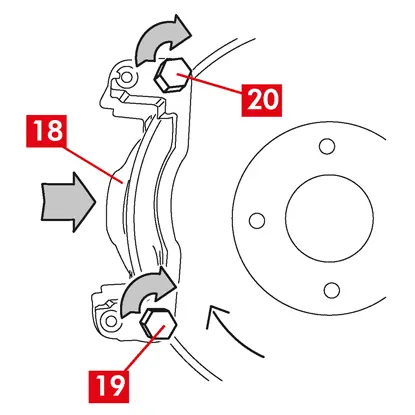
8. Placera det nya bromsoksfästet (punkt 18) genom att föra in det i skivan.
9. Sätt i och närma de två fästbultarna (punkt 19 och 20).
10. Dra åt fästbulten på skivans ingångssida (punkt 19) (i framväxel) med det åtdragningsmoment som rekommenderas av fordonstillverkaren.
11. Dra åt den andra fästbulten 20 (på skivans utloppssida) med det åtdragningsmoment som rekommenderas av fordonstillverkaren.
Använd följande rekommenderade åtdragningsmoment som referens:
| Typ av skruv | Åtdragningsmoment |
| M12x1,25 | 115 Nm |
| M12x1,5 | 125 Nm |
| M14x1,5 | 180 Nm |
| M16x1,5 | 210 Nm |
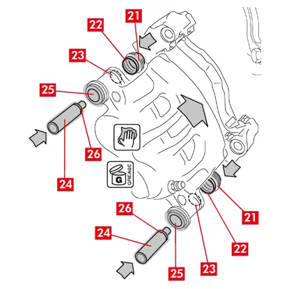
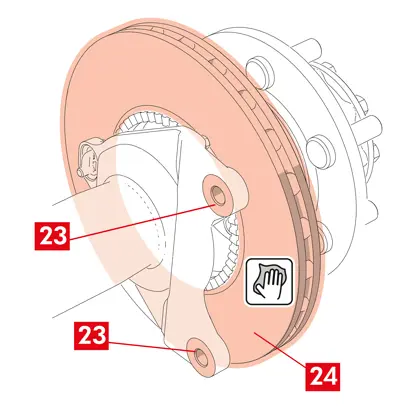
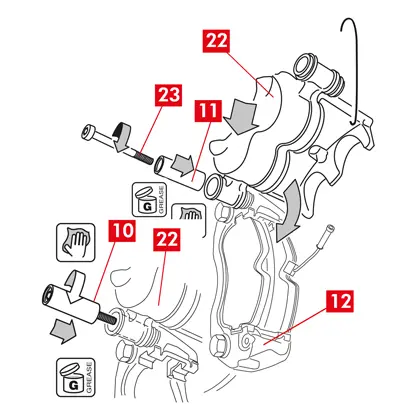
12. Smörj hela den inre ytan på skydden (punkt 21) och kontaktprofilen (punkt 22) med bromsokshuset jämnt.
13. Sätt in skydden (punkt 21) i sätena (punkt 23) på bromsokshuset.
FÖRSIKTIGHET! Kontrollera med fingret att skyddet har satts in och sitter korrekt i bromsokshuset.
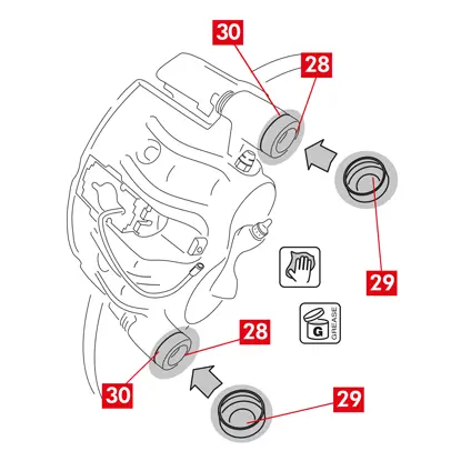
14. Smörj den yttre ytan på bussningarna (punkt 24) och deras säten (punkt 25) i bromsokshuset, sätt in bussningarna i bromsokshuset från skyddets motsatta sida.
15. Skjut bussningarna (punkt 24) tills skydden (punkt 21) passar i sitt säte (punkt 26).
16. Avlägsna eventuellt överflödigt fett.
17. Montera bromsoket på bromsoksfästet genom att gänga igenom och skruva fast skruven eller den inbyggda bussningen på skivans utloppssida (i framväxel).
18. Dra ut bromsokshuset (punkt 27) från bromsoksfästet (punkt 18) genom att vrida den runt styrbussningen tills beläggen går in i bromsoksfästet. Fäst bromsoket på fordonschassit med hjälp av lämpliga stöd.
FÖRSIKTIGHET! Använd inte styrbussningens säte som fästpunkt.
Montering av beläggen
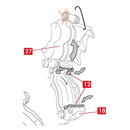
1. Montera fjädrarna på sidan (punkt 12) i bromsokets fäste om lämpligt och tryck till ordentligt så att de sitter fast ordentligt.
2. På bromsok med fyra fjädrar ska fjädrarna alltid monteras med lamellerna vända mot utsidan av bromsoksfästet.
FÖRSIKTIGHET! Observera korrekt monteringsriktning.
VARNING! OM det finns några belägg med en självhäftande sida måste nya belägg monteras. Följ anvisningarna som medföljer reservbelägge.
FÖRSIKTIGHET! Belägget med slitageindikator måste monteras tillbaka i sitt ursprungliga läge innan det demonteras.
3. Sätt tillbaka beläggen (punkt 11) i bromsoksfästet (punkt 18); för bromsok av typ B, använd en skruvmejsel för att öppna fjädrarna på sidan (punkt 12).
VARNING! Eventuella pilar som är stämplade på beläggen måste peka i skivans rotationsriktning.
FARA! Belägg måste sättas in med friktionsmaterialet vänt mot skivan.
VARNING! Eventuella pilar som är stämplade på beläggen måste peka i skivans rotationsriktning.
FARA! Belägg måste sättas in med friktionsmaterialet vänt mot skivan.
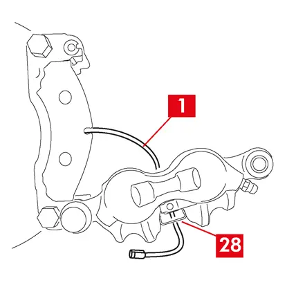
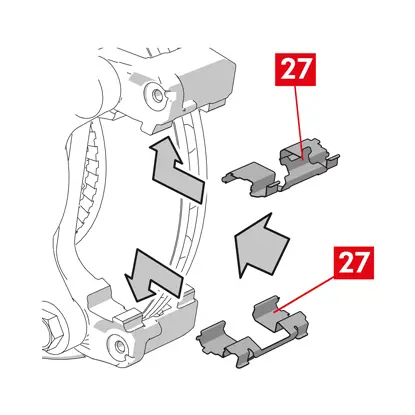
4. Dra slitageindikatorkabeln (punkt 1) genom den avsedda kanalen enligt följande:
För bromsok av typ A - i fjädern (punkt 28).
För bromsok av typ B - i bromsokshuset (punkt 27).
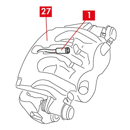

4. Stäng bromsoket försiktigt genom att vrida bromsokshuset (punkt 27) runt den fastskruvade styrbussningen. Om det finns några belägg med en självhäftande sida, var noga med att inte skapa kontakt mellan bromsoket och belägget innan du har slutfört monteringen av bromsoket.
FÖRSIKTIGHET! Stäng bromsoket försiktigt och se till att skyddshöljena på bussningarna inte skadas av stötar mot bromsoksfästet.
FÖRSIKTIGHET! Stäng bromsoket försiktigt och se till att skyddshöljena på bussningarna inte skadas av stötar mot bromsoksfästet.
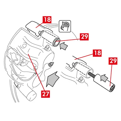
5. Flytta bromsokshuset (punkt 27) mot bromsoksfästet (punkt 18).
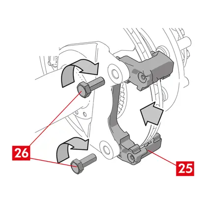
6. Sätt tillbaka styrbussningen (punkt 29) i bromsoksfästet.
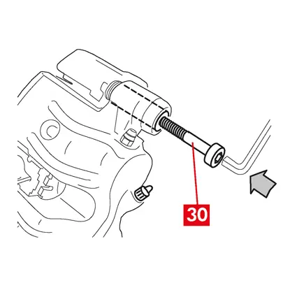
7. Sätt i och skruva i en ny skruv (punkt 30), i förekommande fall.
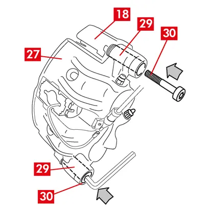
8. Vid byte av bromsok på bakhjul med fjädring och bladfjädrar, måste bromsokshuset (punkt 27) sättas tillbaka på bromsoksfästet (punkt 18), därefter sätts båda styrbussningarna tillbaka (punkt 29) och två nya skruvar (punkt 30) ska sättas i och dras åt, i förekommande fall.
9. Om den ännu inte är fastskruvad, dra åt styrbussningens fästskruv eller den inbyggda styrbussningen på skivans ingångssida (i framväxel). Dra sedan åt den andra skruven eller den andra inbyggda styrbussningen med samma åtdragningsmoment.
10. Dra åt med det åtdragningsmoment som anges i följande tabell:
| Typ | Åtdragningsmoment | |
| Fästskruv | (M8 – CH6) | 32 ÷ 36 Nm |
| Styrbussning med inbyggd skruv | (M8 – CH6) | 32 ÷ 36 Nm |
| Styrbussning med inbyggd skruv | (M10 – CH8) | 65 ÷ 75 Nm |
FARA! Följ den beskrivna åtdragningsordningen, annars kan bromsokets funktion äventyras.
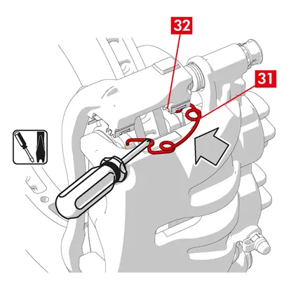
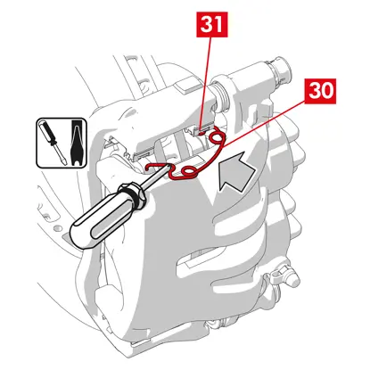
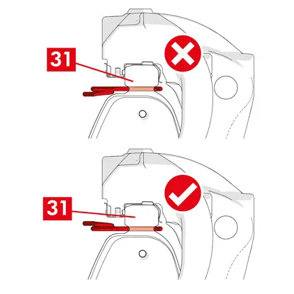
11. Vid fjädrar (punkt 31) som reducerar resterande vridmoment, haka fast fjädern under plattan (punkt 32) på belägget och haka fast undersidan av plattan på det andra belägget med hjälp av en hylsskruvmejsel.
FARA! Felaktig fastsättning av fjädern kan leda till att den frigörs.
FÖRSIKTIGHET! Observera korrekt monteringsriktning.
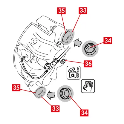
12. Rengör försiktigt delarna (punkt 33) för att säkerställa att de sitter på plats och montera nya skyddskåpor (punkt 34), smörj deras inre yta och bromsokshusets säte med fett som finns i reservdelssatsen.
13. Vrid skyddslocket (punkt 34) så att det fäster helt mot sätet (punkt 35).
14. Återanslut slitageindikatorn, i förekommande fall, till uttageti fordonet, säkra den med ett lätt tryck mot mellanlägget på bromsoket och säkra eventuella fästen på chassit.
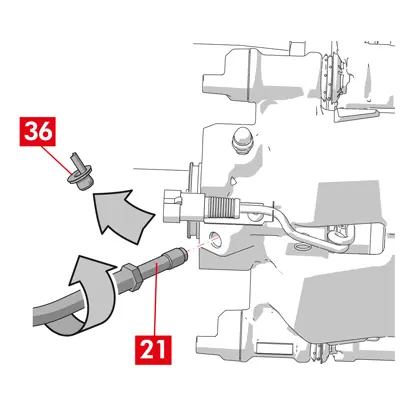
15. Avlägsna skyddslocket från bromsvätskans inloppshål (punkt 36).
16. Återanslut bromsvätskans matningsledning.
17. Ta bort distansen som du tidigare placerade i passagerarutrymmet, vilket frigör pedalen från bromsen och gör att hydraulkretsen kan öppnas igen.
18. Öppna locket till bromsvätskebehållaren.
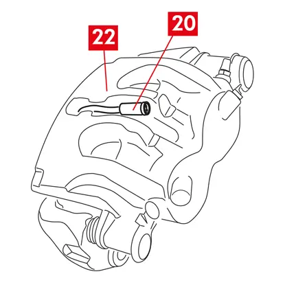
19. Ta bort skyddslocket (punkt 37) och anslut en genomskinlig slang till avtappningspluggen (punkt 38) på bromsoket, vars ändar ska placeras i en behållare för att samla upp eventuell vätska.
20. Öppna avtappningspluggen (punkt 38).
21. Tryck upprepade gånger på fordonets bromspedal tills bromsvätska börjar rinna ut ur avtappningspluggen.
22. Håll ned pedalen och stäng avtappningspluggen. Släpp upp pedalen, vänta några sekunder och upprepa sedan processen tills vätska utan luftbubblor rinner ut och tills bromspedalens normala motstånd och rörelse återställs.
23. Dra åt avtappningspluggen med det åtdragningsmoment som anges i tabellen:
| Avtappningsplugg | M6x1 | M8x1,25 | M10x1 | M12x1 |
| Åtdragningsmoment | 5÷7 Nm | 7÷10 Nm | 17÷20 Nm | 18÷22 Nm |
24. Ta bort det genomskinliga röret och sätt tillbaka skyddskåpan på avtappningspluggen.
25. Upprepa avtappningsproceduren för alla andra avtappningspluggar.
26. Efter avtappningen drar du tillbaka kolvarna i bromsoket helt med hjälp av ett lämpligt verktyg (t.ex. en retraktor) och fyller sedan på vätskenivån enligt tillverkarens rekommendationer.
27. Stäng locket till bromsvätskebehållaren.
28. Med motorn igång, tryck hårt på fordonets bromspedal och kontrollera att det inte finns några vätskeläckage från bromsoket eller onormala tryckförluster i kretsen och att de bakre bromsljusen tänds.
FARA! Om vätska läcker från bromsoket, upprepa alla steg som beskrivs i detta dokument för att lokalisera orsaken och åtgärda problemet.
29. För bromsok med inbyggd parkeringsbroms, anslut parkeringsbromskabelns uttag till motsvarande fäste på bromsoket.
30. Dra åt och lossa parkeringsbromsen upprepade gånger.
31. Sätt tillbaka hjulet.
32. Om beläggen är nya, kör in dem; följ instruktionerna som medföljer reservbeläggen
Nedan följer instruktioner för byte av komponenter för flytande bromsok för nyttofordon (typ ECS53 och ECS60) med inbyggd elektrisk parkeringsmekanism:
1. Ställdonsenhet
2. Belägg
3. Bromsokshus (utan belägg och bromsoksfäste)
4. Bromsoksfäste
2. Belägg
3. Bromsokshus (utan belägg och bromsoksfäste)
4. Bromsoksfäste
VARNING! Läs detta dokument innan du byter ut de reservdelar som ingår i förpackningen. Utför endast de åtgärder som krävs för att byta ut den eller de reservdelar som ingår i förpackningen.
Förfarande för byte
Innan bytet påbörjas, kontrollera att reservdelarna som används för byte är lämpliga för fordonets märke och modell.
VARNING! Vid elektriskt fel, demontera ställdonet och dra tillbaka kolven genom att vrida torxskruven medurs med en lämplig skiftnyckel.
- Notera positionen för alla delvis eller helt demonterade komponenter för korrekt återmontering.
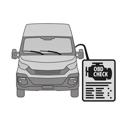
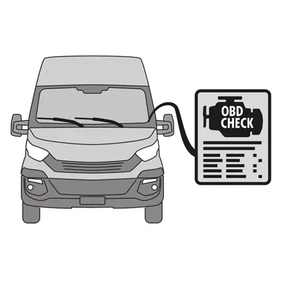
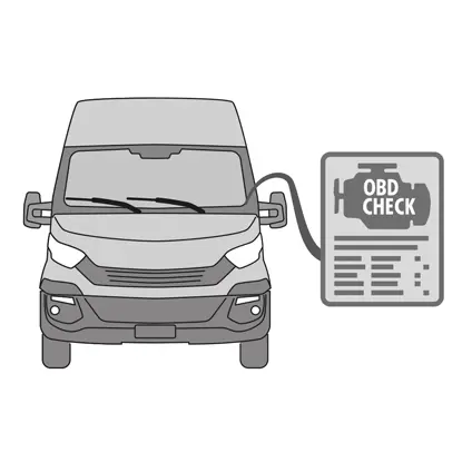
1. Anslut diagnosverktyget (On Board Diagnosis - OBD) till fordonet och sätt det i underhållsläge enligt fordonstillverkarens anvisningar.
FÖRSIKTIGHET! Kontrollera att reservdelen är kompatibel med fordonets programvara.
2. Ta bort hjulet.
3. Lossa ställdonsenhetens elkabel från kabelgenomföringen.
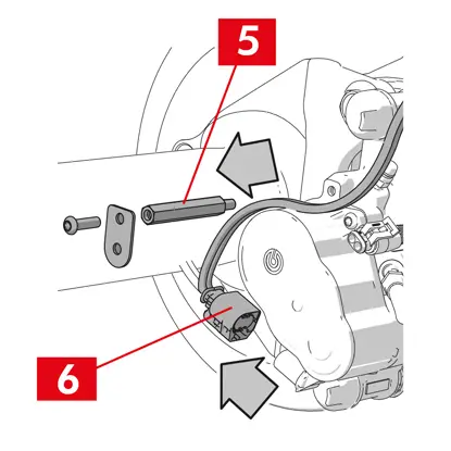
4. För bromsok typ ECS60 lossa och avlägsna kabelgenomföringen (punkt 5).
5. Koppla bort elkabeln (punkt 6) från ställdonet.
VARNING! Kontaktdonet kan vara försett med en säkerhetsspärr.
VARNING! Kontaktdonet kan vara försett med en säkerhetsspärr.
Demontering av ställdonsenheten
VARNING! Fortsätt endast med demonteringen av ställdonsenheten om en separat reservdel finns tillgänglig.
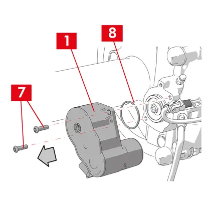
1. Lossa fästskruvarna (punkt 7) från ställdonsenheten (punkt 1).
2. Demontera ställdonsenheten (punkt 1).
3. Ta bort tätningen (punkt 8).
Demontering av beläggen
FÖRSIKTIGHET! Skada inte komponenter som ska återanvändas.
FARA! Bromsvätskans tilloppsledning får inte sträckas.
FARA! Bromsvätskans tilloppsledning får inte sträckas.
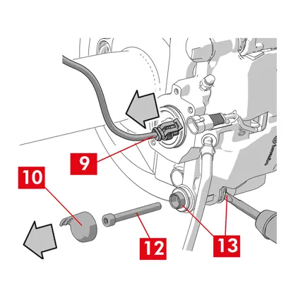
1. Koppla bort slitageindikatorn (punkt 9), i förekommande fall, från kontakten i fordonet, lossa den från mellanlägget som håller fast den vid bromsoket och från alla fästen på chassit.
2. Avlägsna skyddslocket (punkt 10) från den andra bussningen (utgångssida framväxelns varvtalsskiva).
3. Om locket är tillverkat av hårdplast (punkt 11), ta bort det med en skruvmejsel. Locket går sönder om det tas bort.
VARNING! Återanvänd inte det demonterade locket i hårdplast.
4. Lossa och ta bort den andra skruven (punkt 12).
5. För bromsok typ ECS60, använd en skruvmejsel för att bända ut bussningen ur spåret och lossa den från bromsoksfästet.
6. Avlägsna skyddslocket (punkt 14) från den första bussningen (ingångssida framväxelns varvtalsskiva).
7. Lossa den första skruven (punkt 15) helt och ta bort den.
VARNING! Använd en skruvmejsel för att lyfta ut styrbussningarna ur spåren.
8. Ta ut den primära styrbussningen (punkt 16) såpass mycket att den lossnar från bromsoksfästet.
9. Dra ut bromsoket (punkt 3) från bromsoksfästet (punkt 4) och var försiktig så att inte bromsvätskans matningsledning sträcks.
10. Fäst bromsoket på fordonschassit med hjälp av lämpliga stöd.
FÖRSIKTIGHET! Använd inte bussningens säte som fästpunkt.
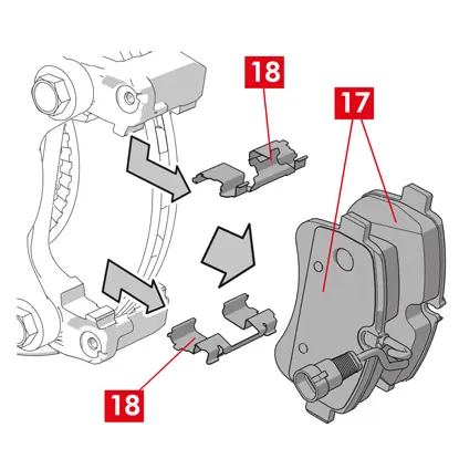
11. Ta bort dynorna (punkt 17) och fjädrarna (punkt 18) utan att skada dem så att du kan montera tillbaka dem på det nya bromsoket.

12. Om de fortfarande är på plats, demontera fjädrarna för reducering av kvarvarande vridmoment (punkt 19).
VARNING! För korrekt återmontering av samma belägg, markera några pilar (om de inte finns) på beläggen med en markör för att ange skivans rotationsriktning.
Demontering av bromsokshuset
1. Placera en distans (punkt 20) i passagerarutrymmet mellan sätet och bromspedalen för att se till att pedalen förblir intryckt under hela tiden som dessa åtgärder pågår.
VARNING! Detta gör att bromsens hydraulkrets kan stängas, vilket förhindrar att bromsvätska läcker ut.
FÖRSIKTIGHET! Under alla faser som beskrivs nedan, se till att bromsvätskan inte kommer i kontakt med delar av fordonet som kan skadas, särskilt lackerade delar. Torka omedelbart av eventuella bromsvätskestänk eller läckage med hushållspapper och rengör med vatten.
2. Lossa matningsledningen (punkt 21) på bromsoket så mycket att du kan skruva av den helt för hand, eftersom det undviker att bromsvätska läcker ut.
3. Lossa försörjningsledningen (punkt 21) helt från bromsoket.
4. Torka omedelbart bort eventuellt läckage av bromsvätska.
5. Håll matningsledningen upphöjd för att förhindra vätskeläckage.
6. Dra bort bromsokshuset (punkt 3).
Demontering av bromsoksfästet
FÖRSIKTIGHET! Håll bromsoksfästet på plats under demonteringen så att det inte kan tappas av misstag.
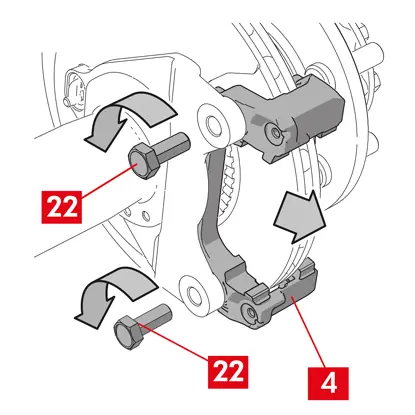
1. Lossa fästskruvarna (punkt 22).
2. Ta bort bromsoksfästet (punkt 4) från navets fäste.
Monteringsprocedur
Montera tillbaka de nya delarna.
1. Rengör noggrant alla komponenter som ska monteras (nya eller tidigare demonterade), bussningssätena och fjädersätena med lämpliga produkter (t.ex. en fuktig trasa).
FARA! Kontrollera att komponenterna är hela och byt ut dem mot nya om de är skadade.
2. Rengör monteringsytorna (punkt 23) på navfästet.
3. Rengör bromsytorna (punkt 24) på skivan med en avfettningsprodukt (t.ex. lösningsmedel SE47).
Montering av bromsoksfäste
1. Placera det nya bromsoksfästet (punkt 25) på navfästet.
2. Sätt i och dra åt fästskruvarna (punkt 26) med det åtdragningsmoment som rekommenderas av fordonstillverkaren.
Montering av bromsbelägg och bromsok
1. Sätt tillbaka fjädrarna (punkt 27) och placera dem rättvända i sina säten.
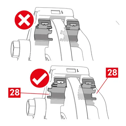
2. För bromsok typ ECS52 med fyra fjädrar, montera alltid fjädrarna med lamellerna (punkt 28) vända mot utsidan av bromsoksfästet.
VARNING! OM det finns några belägg med en självhäftande sida måste nya belägg monteras. Följ anvisningarna som medföljer reservbelägge.
FÖRSIKTIGHET! Belägget med slitageindikator måste monteras tillbaka i sitt ursprungliga läge innan det demonteras.
FARA! Belägg måste sättas in med friktionsmaterialet vänt mot skivan.
3. Sätt tillbaka beläggen (punkt 29) i bromsoksfästet (punkt 25). Använd en skruvmejsel för att öppna fjädrarna på sidan (punkt 27).
4. Vid fjädrar (punkt 30) som reducerar resterande vridmoment, haka fast fjädern under plattan (punkt 31) på belägget och haka fast undersidan av plattan på det andra belägget med hjälp av en hylsskruvmejsel.
FARA! Felaktig fastsättning av fjädern kan leda till att den frigörs.
FARA! Felaktig fastsättning av fjädern kan leda till att den frigörs.
FÖRSIKTIGHET! Observera korrekt monteringsriktning.
FÖRSIKTIGHET! Om bromsoket är nytt får du inte ta bort skyddslocket från vätskeinloppshålet på det nya bromsoket förrän du har anslutit matningsledningen till det.
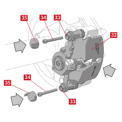
6. Placera bromsokshuset (punkt 32) genom att föra in det i skivan, så att styrbussningarna sammanfaller med hålen på bromsoksfästet.
FÖRSIKTIGHET! Skada inte skydden
7. Skjut in styrbussningarna (punkt 33) i sina lägen på bromsoksfästet.
8. Sätt i och dra åt skruvarna (punkt 34) med ett åtdragningsmoment på 32 ÷ 36 Nm.
9. Placera kåporna (punkt 35).
FÖRSIKTIGHET! Innan du tar bort skyddskåpan, låt påfyllningspunkten vara så hög som möjligt och se till att ingen bromsvätska i bromsoket läcker ut.
10. Återanslut slitageindikatorkabeln, om sådan finns, till uttaget i fordonet, säkra den med ett lätt tryck mot mellanlägget på bromsoket, i förekommande fall, och säkra alla fästen på chassit.
Anslutning av bromsvätskans matningsledning
1. Avlägsna skyddskåpan (punkt 36) från bromsvätskans inloppshål.
2. Koppla tillbaka bromsvätskeledningen (punkt 21).
3. Ta bort distansen som du tidigare placerade i passagerarutrymmet, vilket frigör pedalen från bromsen och gör att kretsen kan öppnas igen.
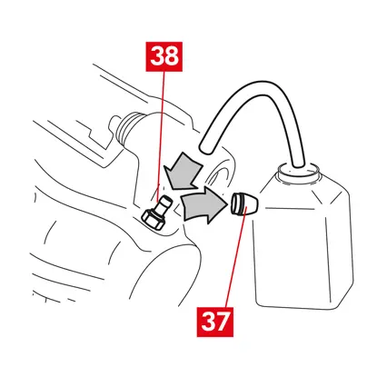
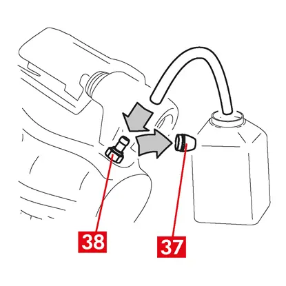
4. Avlägsna skyddskåpan (punkt 37) från avtappningspluggen (punkt 38).
5. Anslut en genomskinlig slang till avtappningspluggen (punkt 38) på bromsoket, vars ändar ska placeras i en behållare för att samla upp eventuell vätska.
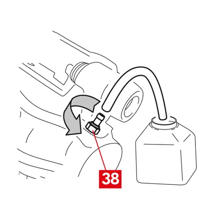
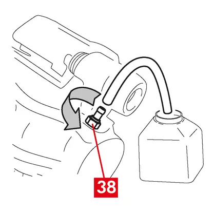
6. Öppna avtappningspluggen (punkt 38).
7. Tryck upprepade gånger på fordonets bromspedal tills bromsvätska börjar rinna ut ur avtappningspluggen.
8. Håll ned pedalen och stäng avtappningspluggen. Släpp upp pedalen, vänta några sekunder och upprepa sedan processen tills vätska utan luftbubblor rinner ut och tills bromspedalens normala motstånd och rörelse återställs.
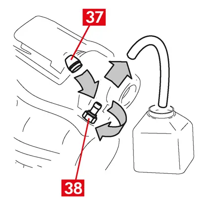
9. Dra åt avtappningspluggen (punkt 38) med det åtdragningsmoment som anges i följande tabell:
| Avtappningstyp | M10x1 |
| Åtdragningsmoment | 12÷16 Nm |
10. Ta bort det genomskinliga röret.
11. Upprepa avtappningsproceduren för alla andra avtappningspluggar.
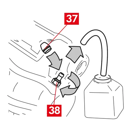
12. Sätt tillbaka skyddskåpan (punkt 37).
13. Efter avtappningen drar du tillbaka kolvarna i bromsoket helt med hjälp av ett lämpligt verktyg (t.ex. en retraktor) och fyller sedan på vätskenivån enligt tillverkarens rekommendationer.
14. Med motorn igång, tryck hårt på fordonets bromspedal och kontrollera att det inte finns några vätskeläckage från bromsoket eller onormala tryckförluster i kretsen och att de bakre bromsljusen tänds.
FARA! Om vätska läcker från bromsoket, upprepa alla steg som beskrivs i detta dokument för att lokalisera orsaken och åtgärda problemet.
Montering av ställdonsenheten
VARNING! Ställdonsenheten kan levereras redan monterad på bromsokshuset.
Montera tillbaka de nya delarna.
- Rengör alla komponenter som du har demonterat innan du monterar tillbaka dem.
FÖRSIKTIGHET! Använd alltid nya skruvar med gänglås. Montera alltid en ny tätning.
FARA! Kontrollera att komponenterna är hela och byt ut dem mot nya om de är skadade
1. Rengör kontaktytan på bromsoket och på ställdonet.
2. Avlägsna eventuella rester av gänglås från gängade skruvsäten.
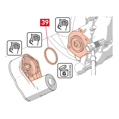
3. Rengör och smörj tätningen (punkt 39) med det medföljande fettet.
4. Smörj den inre diametern på ställdonsenhetens koppling med det medföljande fettet.
VARNING! EUH210 - Säkerhetsdatablad finns tillgängligt på begäran.
VARNING! EUH208 - Innehåller N-alkylerad bensotriazol. Kan orsaka en allergisk reaktion.
5. Placera tätningen (punkt 39) i sitt säte (punkt 40) på bromsokshuset.
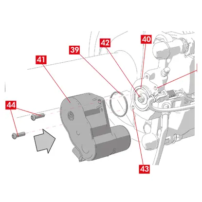
6. Montera ställdonsenheten (punkt 41) på torxskruven (punkt 42) på bromsokshuset.
7. Vrid ställdonsenheten (punkt 41) så att hålen (punkt 43) för fästskruvarna (punkt 44) sammanfaller med deras ursprungliga monteringsläge.
FÖRSIKTIGHET! Undvik att klämma tätningen (punkt 39) vid montering av ställdonsenheten på bromsokshuset.
8. Sätt i och dra åt fästskruvarna (punkt 44) med ett åtdragningsmoment på 7 ÷ 10 Nm.
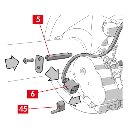
9. Avlägsna skyddslocket (punkt 45) i förekommande fall och anslut elkabeln (punkt 6).
10. Skruva fast kabelgenomföringen (punkt 5) där den tidigare tagits bort.
11. Fäst ställdonsenhetens elkabel (punkt 6) i kabelgenomföringen (punkt 5).
Slutfaser
1. Sätt tillbaka hjulet.
2. Utför återställningsproceduren (monteringskontroll).
3. Återställ vid behov räknarna (återställ interna räknare) enligt fordonstillverkarens anvisningar.
4. Kör in beläggen om det krävs av fordonstillverkaren.
5. Koppla ur diagnosutrustningen. (On Board Diagnosis – OBD).
Nedan följer instruktioner för byte av bromsokhuset för flytande bromsok med 2 eller 4 sidofjädrar och fjädrar för reducering av resterande vridmoment.
Vid byte av endast fästskruvarna, hänvisa endast till relevanta delar.
Förfarande för byte
Innan bytet påbörjas, kontrollera att reservdelarna som används för byte är lämpliga för fordonets märke och modell.
- Notera positionen för alla delvis eller helt demonterade komponenter för korrekt återmontering.
- Ta bort hjulet.
För ECS-bromsok
VARNING! Vid elektriskt fel, demontera ställdonet (punkt 5) och dra tillbaka kolven genom att vrida torxskruven medurs med en lämplig skiftnyckel.
1. Anslut diagnosverktyget (On Board Diagnosis - OBD) till fordonet och sätt det i underhållsläge enligt fordonstillverkarens anvisningar.
FÖRSIKTIGHET! Utan denna funktion kan kolven inte dras tillbaka med utdragsdon eller annat lämpligt verktyg.
FÖRSIKTIGHET! Kontrollera att reservdelen är kompatibel med fordonets programvara.
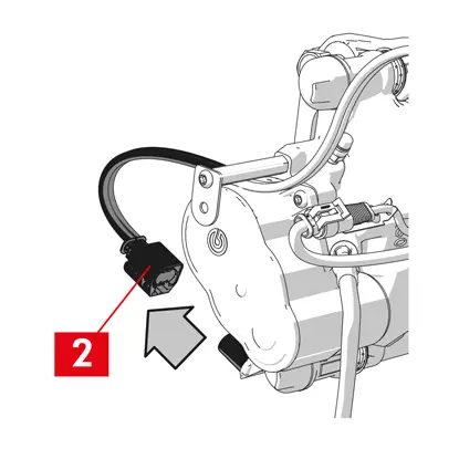
2. Koppla bort elkabeln (punkt 2) från ställdonet.
VARNING! Kontaktdonet kan vara försett med en säkerhetsspärr.
För alla typer av bromsok

1. För bromsok med parkeringsbroms, lossa styrkabeln (punkt 3) från bromsoket.
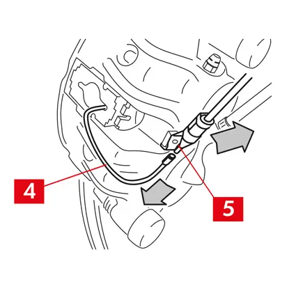
2. Koppla bort slitageindikatorn (punkt 4), i förekommande fall, från kontakten i fordonet, lossa den från mellanlägget (punkt 5) som håller fast den vid bromsoket och från alla fästen på chassit.
3. Ta bort skyddskåporna (punkt 6) från styrbussningarna.
4. Om locket har en förslutningsring (punkt 7), knäpp av locket genom att dra i förslutningsringen (punkt 7) med fingrarna.
5. Om locket är tillverkat av hårdplast (punkt 8), ta bort det med en skruvmejsel. Locket går sönder om det tas bort.
VARNING! Återanvänd inte det demonterade locket i hårdplast.
FÖRSIKTIGHET! Styrbussningen vid demontering måste vara den som gör att bromsokets kropp kan vridas utan att bromsvätskans matningsledning sträcks.
VARNING! Det finns två typer av styrbussningar: med separat skruv, med inbyggd skruv.
VARNING! Återanvänd inte det demonterade locket i hårdplast.
FÖRSIKTIGHET! Styrbussningen vid demontering måste vara den som gör att bromsokets kropp kan vridas utan att bromsvätskans matningsledning sträcks.
VARNING! Det finns två typer av styrbussningar: med separat skruv, med inbyggd skruv.
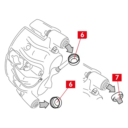
6. Lossa skruven (punkt 9) eller den inbyggda styrbussningen (punkt 10) med en skiftnyckel och ta bort den helt.
7. Om styrbussningen (punkt 11) inte är inkorporerad, dra ut styrbussningen ur bromsokets fäste (punkt 12) genom att trycka ut den ur sitt säte med en skruvmejsel.
8. Vid byte av bromsok på bakhjul med fjädring och bladfjädrar, måste båda styrbussningarna 11 tas bort för att separera bromsokets kropp (punkt 13) helt från bromsokets fäste (punkt 12).
VARNING! Om bromsbeläggen är fastlimmade på bromsoket, lossa dem med en skruvmejsel och se till att inte skada bromsokets gummidelar.
FARA! Om bromsoket öppnas kan fjädrarna som reducerar resterande vridmoment frigörs.
9. Dra ut bromsoket (punkt 13) från bromsoksfästet (punkt 12) genom att vrida det runt den andra styrbussningen tills beläggen (punkt 14) kommer ut ur bromsoksfästet. Fäst bromsoket på fordonschassit med hjälp av lämpliga stöd. Använd inte bussningens säte som fästpunkt.
11. Avlägsna beläggen (punkt 14) utan att orsaka några skador.
12. Markera skivans rotationsriktning på beläggen med en penna för att undvika felaktig återmontering.
14. Om de fortfarande är på plats, demontera fjädrarna för reducering av kvarvarande vridmoment (punkt 15).
15. Placera en distans (punkt 16) i passagerarutrymmet mellan sätet och bromspedalen för att se till att pedalen förblir intryckt under hela tiden som dessa åtgärder pågår.
VARNING! Detta gör att bromsens hydraulkrets kan stängas, vilket förhindrar att bromsvätska läcker ut.
FÖRSIKTIGHET! Under alla faser som beskrivs nedan, se till att bromsvätskan inte kommer i kontakt med delar av fordonet som kan skadas, särskilt lackerade delar. Torka omedelbart av eventuella bromsvätskestänk eller läckage med hushållspapper och rengör med vatten.
FÖRSIKTIGHET! Under alla faser som beskrivs nedan, se till att bromsvätskan inte kommer i kontakt med delar av fordonet som kan skadas, särskilt lackerade delar. Torka omedelbart av eventuella bromsvätskestänk eller läckage med hushållspapper och rengör med vatten.
16. Lossa matningsledningen (punkt 17) på bromsoket så mycket att du kan skruva av den helt för hand, eftersom det undviker att bromsvätska läcker ut.
17. Lossa helt och ta bort skruven (punkt 9) eller den inbyggda styrbussningen (punkt 10).
18. Om styrbussningen (punkt 11) inte är inkorporerad, dra ut styrbussningen ur bromsokets fäste (punkt 12) genom att trycka ut den ur sitt säte med en skruvmejsel.
19. Dra ut bromsoket (punkt 13) från bromsoksfästet (punkt 12) och var försiktig så att inte bromsvätskans matningsledning sträcks.
20. Lossa försörjningsledningen (punkt 17) helt från bromsoket.
21. Torka omedelbart bort eventuellt läckage av bromsvätska.
22. Håll matningsledningen upphöjd för att förhindra bromsvätskeläckage.
23. Dra bort det bromsok som ska bytas ut.
24. För bromsok med inbyggd parkeringsbroms, koppla bort parkeringsbromskabeln från motsvarande fäste på bromsoket.
25. Rengör bromsytorna på skivan med en avfettningsprodukt (t.ex. lösningsmedel SE47).
Montering av beläggen
FÖRSIKTIGHET! OM det finns några belägg med en självhäftande sida måste nya belägg monteras. Följ anvisningarna som medföljer reservbelägge.
1. Kontrollera att fjädrarna är korrekt placerade. För bromsok med fyra fjädrar, se till att lamellerna alltid är vända mot utsidan av bromsokets fäste.
FÖRSIKTIGHET! Felaktig placering av fjädern kan leda till personskador.
2. Sätt i dynorna (punkt 14) i bromsoksfästet (punkt 12). Använd en skruvmejsel för att trycka in sidfjädrarna.
VARNING! Eventuella pilar som är stämplade på beläggen måste peka i skivans rotationsriktning.
FARA! Belägg måste sättas in med friktionsmaterialet vänt mot skivan.
FÖRSIKTIGHET! Belägget med slitageindikator måste monteras tillbaka i sitt ursprungliga läge innan det demonteras.
VARNING! Eventuella pilar som är stämplade på beläggen måste peka i skivans rotationsriktning.
FARA! Belägg måste sättas in med friktionsmaterialet vänt mot skivan.
FÖRSIKTIGHET! Belägget med slitageindikator måste monteras tillbaka i sitt ursprungliga läge innan det demonteras.
3. I förekommande fall, montera slitageindikatorn (punkt 20) på beläggen mittemot kolvarna och byt ut den vid behov.
FÖRSIKTIGHET! När slitindikatorns uttag fästs, se till att den mest utskjutande delen är vänd mot friktionsytan på belägget.
FÖRSIKTIGHET! När slitindikatorns uttag fästs, se till att den mest utskjutande delen är vänd mot friktionsytan på belägget.
Montering av bromsokshus
FÖRSIKTIGHET! För bromsok med parkeringsbroms: när bromsoket är demonterat från bromsskivan och/eller bromsbeläggen saknas, flytta inte kolven vare sig hydrauliskt eller med spaken eftersom detta kan skada fjädern och/eller orsaka bromsvätskeläckage.
1. Torka av monteringsytorna (punkt 21) på bromsokets fäste med bromsokshuset (styrsäten) med en fuktig trasa.
FÖRSIKTIGHET! Använd inte produkter som kan skada skyddshöljet, t.ex. nitro-tetrakloretylen, thinner, bensin etc.
2. Rengör och smörj in hela den inre ytan på locken, den yttre ytan på styrbussningarna och deras säten i bromsokshuset med jämnt fördelat fett.
3. Placera det nya bromsokshuset (punkt 22) och sätt en av de två styrbussningarna (punkt 10) i sätet på bromsokets fäste (punkt 12).
FÖRSIKTIGHET! Ta inte bort skyddslocket från bromsvätskans inloppshål förrän slangen är definitivt ansluten.
FÖRSIKTIGHET! Ta inte bort skyddslocket från bromsvätskans inloppshål förrän slangen är definitivt ansluten.
4. Vid icke inkorporerad styrbussning (punkt 11), montera och dra åt en ny skruv (punkt 23).
5. Stäng bromsoket försiktigt genom att vrida bromsokshuset (punkt 22) runt den placerade styrbussningen.
FÖRSIKTIGHET! Stäng bromsoket försiktigt och se till att skyddshöljena på bussningarna inte skadas av stötar mot bromsokshållaren. Byt ut skydden vid behov.
VARNING! Om det finns några belägg med en självhäftande sida, var noga med att inte skapa kontakt mellan huset och belägget innan du har slutfört monteringen av bromsoket.
6. För in slitageindikatorns sond (punkt 20) genom det avsedda hålet i bromsokshuset (punkt 22).
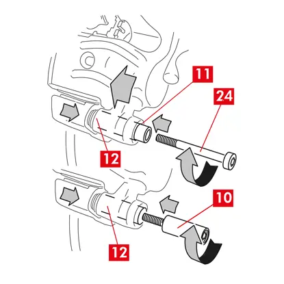
7. Sätt tillbaka den andra styrbussningen (punkt 10) i bromsoksfästet (punkt 12).
8. Vid icke inkorporerad styrbussning (punkt 11), montera och dra åt en ny skruv (punkt 24).
FÖRSIKTIGHET! Vid byte av bromsok på bakhjul med fjädring och bladfjädrar, måste bromsokshuset sättas tillbaka på bromsoksfästet, därefter sätts båda styrbussningarna tillbaka och två nya skruvar ska sättas i och dras åt.
9. Dra åt styrbussningens fästskruv eller den inbyggda styrbussningen (punkt 24) på skivans ingångssida (i framväxel). Dra sedan åt den andra skruven eller den inbyggda styrbussningen (punkt 25) med samma åtdragningsmoment.
10. Dra åt med det åtdragningsmoment som anges i följande tabell:
| Typ | Åtdragningsmoment | |
| Fästskruv | (M8 – CH6) | 32 ÷ 36 Nm |
| Styrbussning med inbyggd skruv | (M8 – CH6) | 32 ÷ 36 Nm |
| Styrbussning med inbyggd skruv | (M10 – CH8) | 65 ÷ 75 Nm |
FARA! Följ den beskrivna åtdragningsordningen, annars kan bromsokets funktion äventyras.
11. Vid fjädrar (punkt 26) som reducerar resterande vridmoment, haka fast fjädern under plattan (punkt 27) på belägget och haka fast undersidan av plattan på det andra belägget med hjälp av en hylsskruvmejsel.
FARA! Felaktig fastsättning av fjädern kan leda till att den frigörs.
FÖRSIKTIGHET! Observera korrekt monteringsriktning.
12. Rengör försiktigt delen (punkt 28) för att säkerställa att den sitter på plats och montera nya skyddskåpor (punkt 29), smörj deras inre yta och bromsokshusets säte med fett som finns i reservdelssatsen.
VARNING! EUH210 - Säkerhetsdatablad finns tillgängligt på begäran.
VARNING! EUH208 - Innehåller N-alkylerad bensotriazol. Kan orsaka en allergisk reaktion.
VARNING! EUH208 - Innehåller N-alkylerad bensotriazol. Kan orsaka en allergisk reaktion.
13. Vrid skyddslocken (punkt 29) så att de fäster helt mot sätet (punkt 30).
14. Återanslut slitageindikatorn, i förekommande fall, till uttageti fordonet, säkra den med ett lätt tryck mot mellanlägget på bromsoket och säkra eventuella fästen på chassit.
15. Avlägsna skyddslocket från bromsvätskans inloppshål.
16. Återanslut bromsvätskans matningsledning.
17. Ta bort distansen som du tidigare placerade i passagerarutrymmet, vilket frigör pedalen från bromsen och gör att kretsen kan öppnas igen.
För bromsok med en parkeringsbroms
FÖRSIKTIGHET! Innan du monterar kolven med beläggen, kontrollera att bromsoksfästet, beläggen och skivan finns på plats.
- Använd hävarmen för att montera kolven med beläggen.
FÖRSIKTIGHET! Hydraulisk drift är endast tillåten när kolven är mindre än 1 mm från beläggen.
För alla typer av bromsok
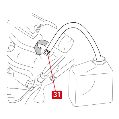
1. Anslut en genomskinlig slang till avtappningspluggen (punkt 31) på bromsoket, vars ändar ska placeras i en behållare för att samla upp eventuell vätska.
2. Öppna avtappningspluggen (punkt 31).
3. Tryck upprepade gånger på fordonets bromspedal tills bromsvätska börjar rinna ut ur avtappningspluggen.
4. Håll ned pedalen och stäng avtappningspluggen. Släpp upp pedalen, vänta några sekunder och upprepa sedan processen tills vätska utan luftbubblor rinner ut och tills bromspedalens normala motstånd och rörelse återställs.
5. Dra åt avtappningspluggen (punkt 31) med det åtdragningsmoment som anges i tabellen:
| Avtappningsplugg | M6x1 | M8x1,25 | M10x1 | M12x1 |
| Åtdragningsmoment | 5÷7 Nm | 7÷10 Nm | 17÷20 Nm | 18÷22 Nm |
6. Ta bort det genomskinliga röret.
7. Upprepa avtappningsproceduren för alla andra avtappningspluggar.
8. Efter avtappningen drar du tillbaka kolvarna i bromsoket helt med hjälp av ett lämpligt verktyg (t.ex. en retraktor) och fyller sedan på vätskenivån enligt tillverkarens rekommendationer.
9. Stäng locket till bromsvätskebehållaren.
10. Med motorn igång, tryck hårt på fordonets bromspedal och kontrollera att det inte finns några vätskeläckage från bromsoket eller onormala tryckförluster i kretsen och att de bakre bromsljusen tänds.
FARA! Om vätska läcker från bromsoket, upprepa alla steg som beskrivs i detta dokument för att lokalisera orsaken och åtgärda problemet.
För bromsok med en parkeringsbroms
- Återanslut slitageindikatorn, i förekommande fall, till uttageti fordonet, säkra den med ett lätt tryck mot mellanlägget på bromsoket och säkra eventuella fästen på chassit.
- Återställ korrekt spänning på styrkabeln.
- Manövrera parkeringsbromsspaken i fordonshytten upprepade gånger tills det vanliga slaget har återställts.
För ECS-bromsok
1. Avlägsna skyddslocket (i förekommande fall) och anslut elkabeln (punkt 2).
2. Utför återställningsproceduren (monteringskontroll).
3. Återställ vid behov räknarna (återställ interna räknare) enligt fordonstillverkarens anvisningar.

4. Kör in beläggen om det krävs av fordonstillverkaren.
5. Koppla ur diagnosutrustningen (On Board Diagnosis - OBD).
För alla typer av bromsok
1. Sätt tillbaka hjulet.
2. Om beläggen är nya, kör in dem; följ instruktionerna som medföljer reservbeläggen
2. Om beläggen är nya, kör in dem; följ instruktionerna som medföljer reservbeläggen
Garantibegränsningar
Denna garanti omfattar alla fel som uppstår inom två år från det att varan levererats. Konsumenten är skyldig att anmäla felet till säljaren inom två månader från den dag då felet upptäcktes, utan att detta påverkar det faktum att tidsfristen för att vidta åtgärder i syfte att avhjälpa felet är tjugosex månader från det att varan levererades. I händelse av bristande överensstämmelse har användaren rätt till reparation eller byte av varan, eller till en lämplig prisreduktion eller uppsägning av kontraktet, i enlighet med art. 130 i konsumentköplagen, i tillämpliga fall.
Denna garanti utgör den enda garanti som ger för denna produkt och ersätter alla andra garantier, både muntliga och skriftliga.
I händelse av påträffade defekter ska användaren:
- med risk för ogiltigförklaring, underrätta tillverkaren och distributören skriftligen inom sextio dagar. Samtidigt ska användaren tillhandahålla en beskrivning av felet på produkten eller på de delar som returneras, och ett inköpsbevis från den ursprungliga användaren som identifierar både produkten och inköpsdatumet (oavsett om den köpts i detaljhandeln eller sålts av en distributör som en del av installationen av produkten);
- att skicka produkten som antas vara defekt till Brembo S.p.A. till huvudkontoret på adressen via Brembo 25 -24035 Curno (BG) - Italien, via distributionskedjan.
Garantin gäller inte för:
- skada på produkten som helt eller delvis orsakats av felaktig användning, olycka, brand, kemisk korrosion, användning för andra ändamål än de avsedda, olaglig användning, användning av en annan modell än den avsedda, felaktig installation, installation i strid med tillverkarens anvisningar eller bristande underhåll av produkten enligt tillverkarens anvisningar i de medföljande instruktionerna;
- klagomål som rör komfort, förekomst av buller, vibrationer eller hårda köregenskaper.
Produkten har utformats och tillverkats för den specifika modell och användning som anges i Brembos kataloger och/eller av Brembos produktdistributörer, som båda finns tillgängliga på Brembos webbplats (www.brembo.com). Produkten ska användas i enlighet med gällande lagar i de stater och/eller länder där det fordon som produkten är installerad på används, inklusive, men inte begränsat till efterlevnad av bestämmelserna i trafikförordningen och efter erhållande av berättigande/godkännande, tillstånd eller licens som krävs av staten och/eller landet.
För produkter som säljs inom Europeiska unionens medlemsländer gäller dessa garantibegränsningar i enlighet med bestämmelserna i rådets direktiv 85/374/EEG av den 25 juli 1985.
För produkter som säljs inom USA:s territorium gäller dessa garantibegränsningar i enlighet med tillämplig federal eller delstatlig lagstiftning.
Allmän information och säkerhetsinformation
Denna Brembo-produkt har utformats för att uppfylla alla tillämpliga säkerhetsstandarder. Produkterna är inte avsedda att användas på annat sätt än för det specifika ändamål som de har konstruerats och tillverkats för. Användning för något annat ändamål eller modifiering eller manipulering av produkten kan påverka produktens prestanda och kan göra produkten osäker.
Sådan ändring eller felaktig användning upphäver den begränsade garantin och kan leda till att den som använder produkten blir ansvarig för personskada eller egendomsskada på andra.
I dessa instruktioner betyder "FARA!" förfaranden som, om de inte följs, med stor sannolikhet kan orsaka allvarliga personskador eller dödsfall.
“FÖRSIKTIGHET” betyder åtgärder som, om de inte följs, kan leda till fysiska skador, medan "VARNING!" betyder åtgärder som, om de inte följs, kan orsaka skador på fordonet.
FARA!
Innan bytet påbörjas, kontrollera att reservdelarna är lämpliga för fordonets märke och modell. Denna produkt är avgörande för säker drift av det fordon som den är installerad på, och den är avsedd att installeras endast av en skicklig, kvalificerad person som har utbildats och/eller har erfarenhet av den installation och användning som produkten är avsedd för.
Installatören måste vara utrustad med rätt verktyg för sitt yrke och ha kunskap och erfarenhet av att hantera fordonsreparationer. Felaktig installation, oavsett om den orsakas av att dessa instruktioner inte har följts noggrant och fullständigt eller på annat sätt, upphäver den begränsade garantin och kan medföra att installatören blir ersättningsskyldig i händelse av personskada eller skada på egendom.
Brembo ansvarar inte för materialskador eller personskador som orsakas av en person som kör ett fordon på vilket en ersättningsprodukt har installerats på ett felaktigt sätt.
Den använda produkten som ersätts av denna produkt får inte installeras på någon annan produkt. Detta kan leda till materiella skador och personskador, inklusive dödsfall.
Kontrollera alltid att bromsvätskenivån i behållaren ligger mellan de minimi- och maximinivåer som anges på behållaren. En felaktig nivå kan orsaka bromsvätskeläckage eller minskad effektivitet i bromssystemet. För mycket eller för lite bromsvätska i behållaren kan leda till att bromsarna inte fungerar som de ska, vilket kan leda till personskador eller dödsfall.
FÖRSIKTIGHET!
Utbytta delar måste skaffas bort i enlighet med gällande lagstiftning.
Det är viktigt att undvika kraftiga slag mot och/eller skador på produkten, dess delar och komponenter, eftersom detta kan försämra deras effektivitet och leda till att de inte fungerar som de ska. Byt vid behov ut skadade delar eller komponenter. För att undvika skador rekommenderar vi följande:
- Använd lämplig utrustning för att förhindra inandning av damm som uppstår vid rengöring av delarna.
- Använd alltid handskar vid demontering och montering av komponenter med vassa kanter.
- Låt inte hudytan komma i direkt kontakt med friktionsmaterialet i belägg och bromsbackar eftersom detta kan orsaka nötningar.
- För inte in händerna i beläggens säte vid demontering av bromsokets kolvar med tryckluft eftersom det finns risk för att händerna kläms.
- Undvik direktkontakt med bromsvätskan eftersom den kan orsaka irritation på hud och ögon. Vid oavsiktlig kontakt, rengör noggrant i enlighet med anvisningarna från tillverkaren av fordonet eller bromsvätskan.
- Utsätt inte de elektriska komponenterna för elektrostatiska laddningar eller stötar som kan skada plastdelarna.
- Skydda de demonterade elektriska komponenterna mot fukt.
- Se till att alla elektriska kontakter är korrekt anslutna och kontrollera att varningslamporna tänds. Om de inte tänds kan det faktum att varningslamporna inte fungerar leda till att bromssystemets effektivitet minskar eller att bromssignalerna inte fungerar.
- Undvik att fett och andra smörjmedel kommer i kontakt med bromsytorna på bromsskivan, trumman, beläggen och och bromsbackarna eftersom detta kan påverka bromssystemets effektivitet och orsaka fysiska skador.
- Använd inte vassa verktyg för att montera gummikomponenter eftersom det kan skada dem. Se till att alla skadade delar byts ut.
Garanti
Vi garanterar att produkten uppfyller tillverkarens specifikationer och att den är fri från material- och tillverkningsfel. Garantin har en begränsad giltighetstid på två år från inköpsdatumet eller en längre period som fastställs i lag. Garantin har en begränsad giltighetstid på två år från inköpsdatumet eller en längre period som fastställs i lag. Om ett fel upptäcks måste det anmälas inom 60 dagar från upptäckten och inom två år från inköpsdatumet. Om felet bekräftas och omfattas av garantin kommer produkten att repareras eller ersättas med en ny eller grundligt renoverad produkt. Garantin täcker inte skador som helt eller delvis orsakats av felaktig användning, brand, kemisk korrosion, olaglig användning eller för andra ändamål än de avsedda, användning på en annan modell än den avsedda, felaktig installation eller i strid med vad som anges av tillverkaren eller underlåtenhet att underhålla produkten enligt tillverkarens anvisningar i de medföljande instruktionerna.
Är det något annat du vill fråga oss?
Kontakta Brembo tekniksupport. Våra tekniker kommer att kontakta dig så snart som möjligt!