


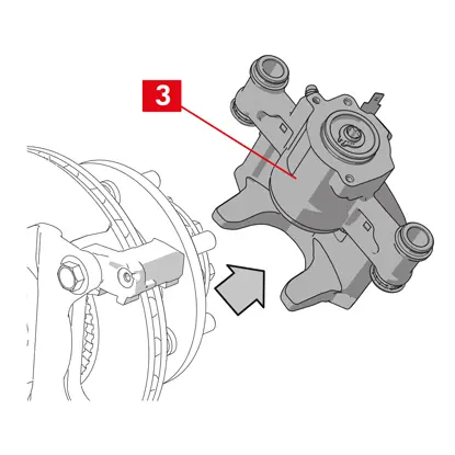
Instructies voor de vervanging van de remklauwen op personenauto’s en lichte bedrijfsvoertuigen
Lees alle instructies zorgvuldig en neem ze nauwgezet in acht. Dezelfde instructies zijn opgenomen in de verpakking van de remklauw. Vergeet niet om ze voor de gehele levenscyclus van het product te bewaren. Overhandig ze aan de nieuwe eigenaar als u uw voertuig verkoopt.
Deze montage-instructies zijn een richtlijn voor standaard reparatiewerkzaamheden en houden geen rekening met eventuele speciale kenmerken die van toepassing kunnen zijn op andere remsystemen. De speciale instructies verstrekt door de fabrikanten van de voertuigen en remsystemen moeten strikt in acht worden genomen.
Dit document verstrekt de instructies voor de vervanging van remklauwen:
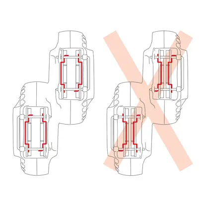
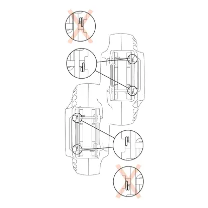
1. Remklauwen met enkele schijf
2. Vaste remklauwen met dubbele schijf
3. Zwevende remklauwen met radiaal gemonteerde remblokken, type 2x60/68.
2. Vaste remklauwen met dubbele schijf
3. Zwevende remklauwen met radiaal gemonteerde remblokken, type 2x60/68.
Alle informatie van dit instructieblad is van toepassing op alle drie soorten remklauwen, tenzij anders aangegeven.
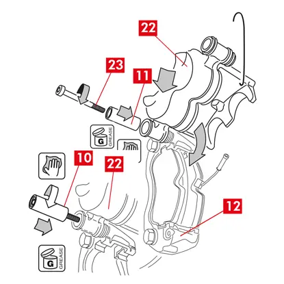
Vervangingsprocedure
Voordat de vervanging wordt gestart, moet gecontroleerd worden of de voor de vervanging gebruikte reserveonderdelen geschikt zijn voor het merk en model van het voertuig.
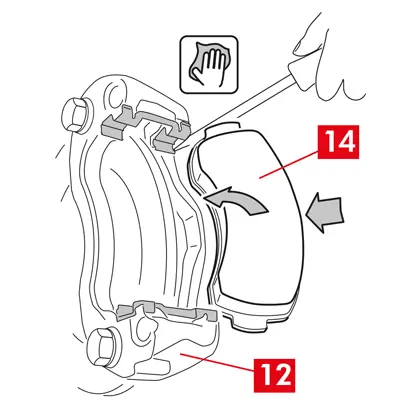
- Verwijder het wiel.
- Noteer de stand van alle gedeeltelijk of volledig gedemonteerde onderdelen, ten behoeve van de correcte terugplaatsing.
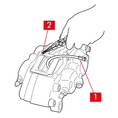
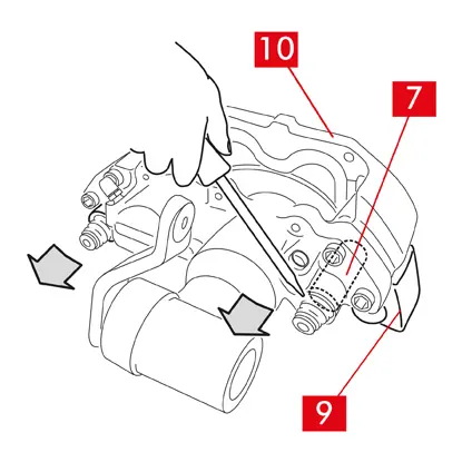
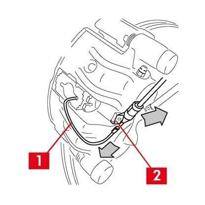
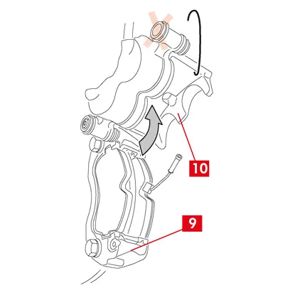
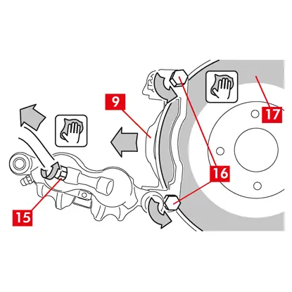
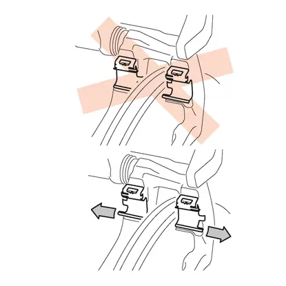
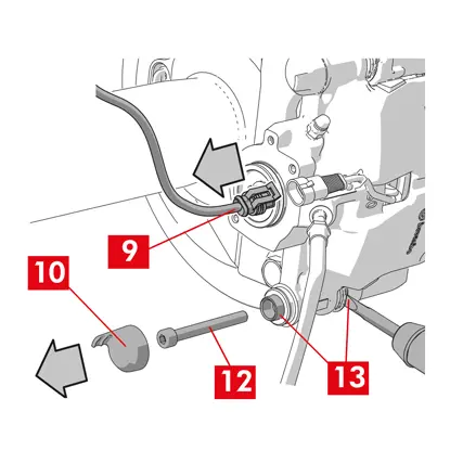
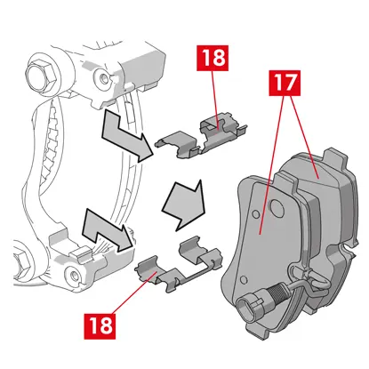
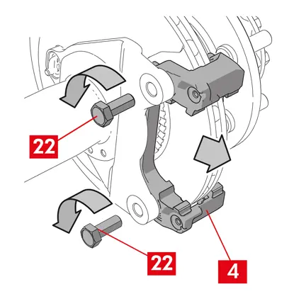
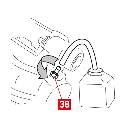
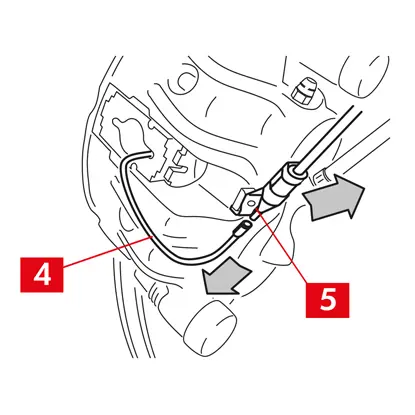
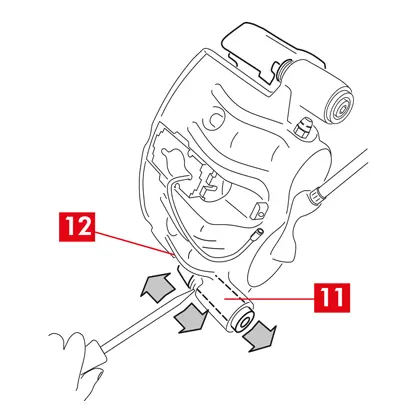
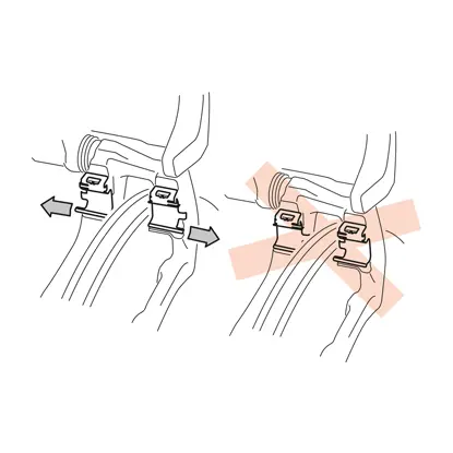
1. Koppel de kabel van de slijtage-indicator (punt 1), indien aanwezig, los van de klem in het voertuig en maak hem los van eventuele bevestigingen op het chassis en de remklauw.
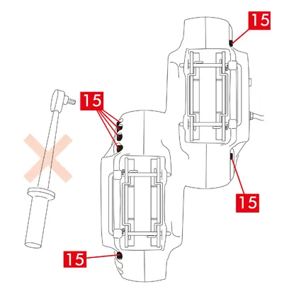
2. Voor modellen voorzien van veiligheidssplitpennen (punt 2) moeten deze met een tang verwijderd worden.
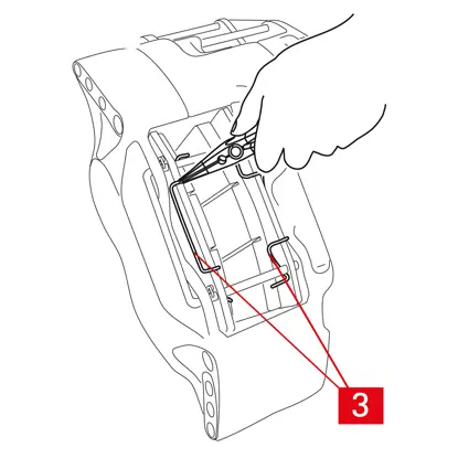
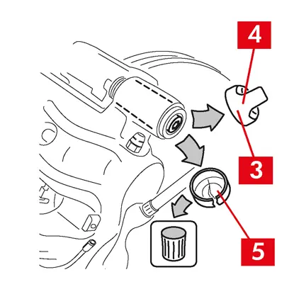
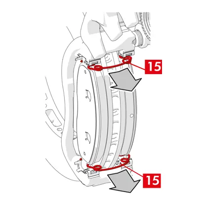
3. In het geval van remklauwen met dubbele schijf, moeten de veren (punt 3) met een tang verwijderd worden.
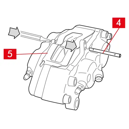
4. Verwijder de pen(nen) (punt 4) met behulp van een hamer en een pendrijver. Trek volledig uit met de hand, maar let op dat de veren (punt 5) op hun plaats blijven.
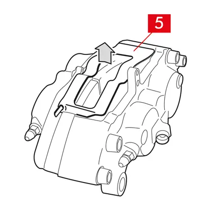
5. Verwijder de veer (veren) (punt 5). Controleer het vloeistofpeil. Open de dop van het remvloeistofreservoir.
OPGELET! De hieronder beschreven stappen voor het terugtrekken van de zuiger veroorzaken een stijging van het vloeistofpeil in het reservoir. Zorg ervoor dat er geen remvloeistof zal lekken omdat hierdoor de gelakte delen van het voertuig beschadigd worden
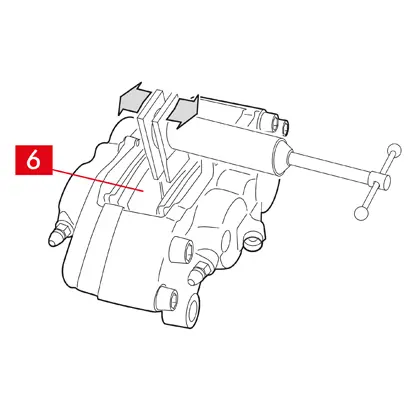
VASTE REMKLAUWEN type A B
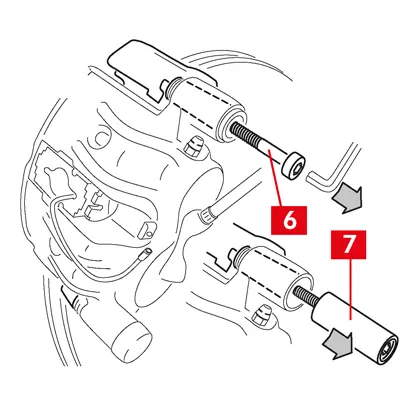
1. Trek de zuigers enigszins weg met behulp van een zuigertang of een ander geschikt gereedschap, door te drukken op de remblokken (punt 6).
Het terugtrekken van de zuiger moet er vervolgens voor zorgen dat de remklauw loskomt van de schijf.
2. Als het ontwerp van de remklauw dit toelaat, verwijder dan de remblokken. Verwijder de anders na de demontage van de remklauw. Als u van plan bent de remblokken opnieuw te gebruiken, markeer dan daarop de draairichting van de schijf met een marker.
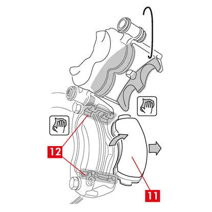
ZWEVENDE REMKLAUWEN type C
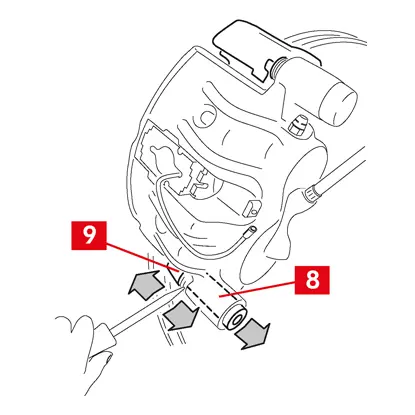
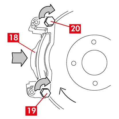
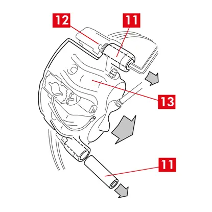
1. Neem de remblokken uit terwijl u tegelijkertijd het remklauwlichaam naar achteren en voren beweegt op de geleidebussen (punt 7). De verschuiving van het remklauwlichaam zorgt ervoor dat de remblokken enigszins van de schijf worden verwijderd, waardoor ze gemakkelijker kunnen worden uitgenomen.
Als de door de slijtage van de schijf veroorzaakte deuk de verwijdering van de remblokken belemmert, moet het remklauwlichaam gedemonteerd worden:
1. Demonteer de schroeven (punt 8) met gebruik van een sleutel
2. Gebruik een schroevendraaier om de geleidebussen uit de betreffende zittingen te wrikken.
3. Neem de geleidebussen (punt 7) voldoende ver uit om ze los te kunnen maken van de remklauwbeugel (punt 9).
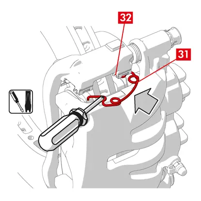
4. Scheid het remklauwlichaam (punt 10) volledig van de remklauwbeugel (punt 9) en hang het op aan het chassis van het voertuig met behulp van een S-vormige haak.
5. Verwijder de remblokken.
6. Als u van plan bent de remblokken opnieuw te gebruiken, markeer dan daarop de draairichting van de schijf met een marker.
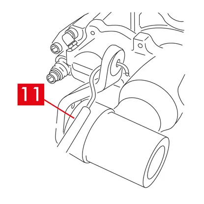
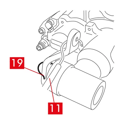
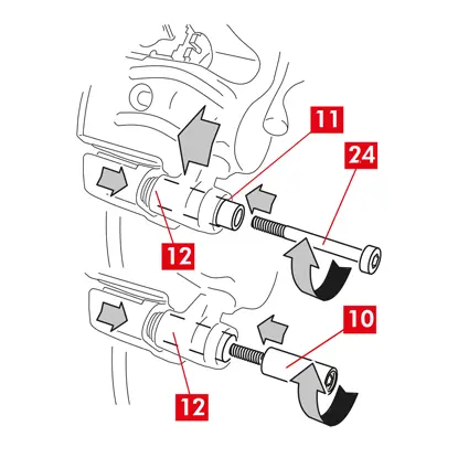
7. Voor achterste remklauwen (met parkeermechanisme) moet de kabel voor parkeerregeling (punt 11) worden losgekoppeld.
GEVAAR! De remvloeistofleidingen moeten los en niet uitgerekt blijven. Als u de leidingen uitrekt, kunnen ze breken en kan er remvloeistof gemorst worden.
Voor alle soorten remklauwen
1. Sluit de dop van het remvloeistofreservoir.
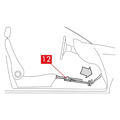
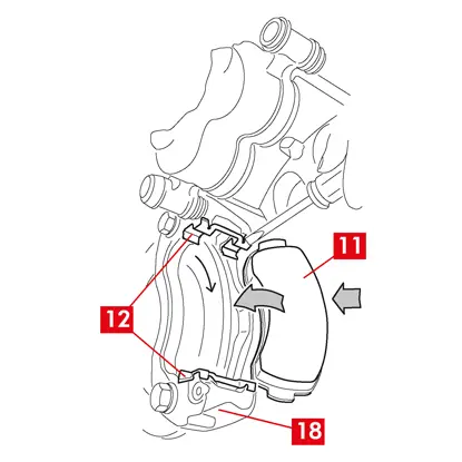
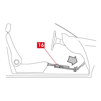
2. Plaats in de passagiersruimte een afstandshouder (punt 12) tussen de stoel en het rempedaal om ervoor te zorgen dat het pedaal gedurende deze handelingen ingetrapt blijft.
WAARSCHUWING! Dit zorgt ervoor dat het hydraulische remcircuit gesloten wordt en het lekken van remvloeistof wordt voorkomen.
OPGELET! Zorg er tijdens alle hieronder beschreven fasen voor dat de remvloeistof niet in contact komt met onderdelen van het voertuig die hierdoor beschadigd kunnen raken, met name de gelakte onderdelen. Per ongeluk gemorste spatten of lekken van remvloeistof moeten onmiddellijk worden opgenomen met een doek/keukenpapier, om vervolgens te reinigen met water.
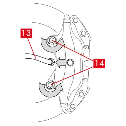
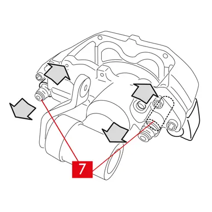
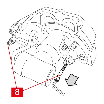
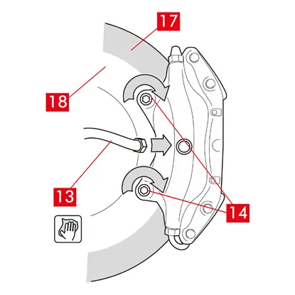
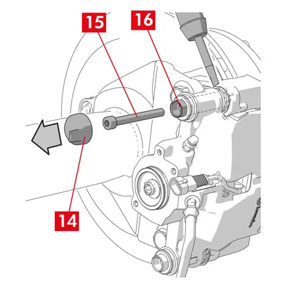
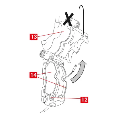
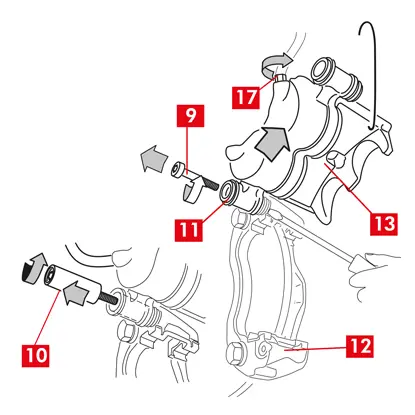
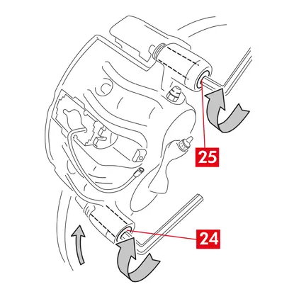
3. Ontspan de toevoerleiding (punt 13) op de remklauw voldoende om deze volledig met de hand los te kunnen schroeven, maar voorkom dat er remvloeistof uit kan lekken.
4. Draai de bevestigingsschroeven (punt 14) los met een steeksleutel en verwijder de remklauw vanaf de as.
5. OPGELET! In het geval van remklauwen met dubbele schijf moeten alleen de bevestigingsschroeven van de as gedemonteerd worden. Demonteer niet de schroeven (punt 15) waarmee de halve remklauwen zijn gekoppeld.
6. Maak de toevoerleiding (punt 13) volledig los van de remklauw.
7. Neem eventueel gelekte remvloeistof onmiddellijk op.
8. Houd de toevoerleiding omhoog om het lekken van de vloeistof te voorkomen.
9. Trek de te vervangen remklauw weg.
9. Trek de te vervangen remklauw weg.
Montageprocedure
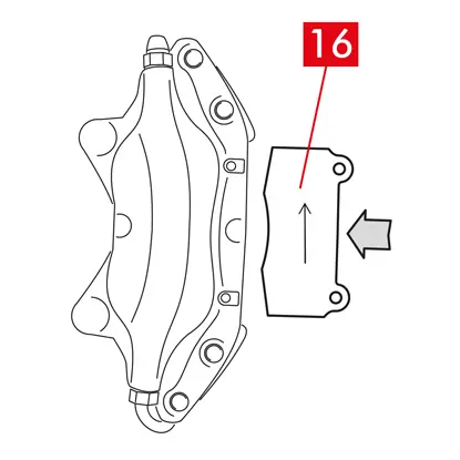
1. Plaats de remblokken (punt 16) in de nieuwe remklauw.
WAARSCHUWING! Eventuele op de remblokken aangegeven pijlen moeten in de draairichting van de schijf wijzen.
GEVAAR! Remblokken moeten met het frictiemateriaal naar de schijf toe geplaatst worden.
2. WAARSCHUWING! Als het ontwerp van de remklauw dat toestaat, kunnen de remblokken ook na de montage van de remklauw worden aangebracht, onmiddellijk na de stap “aanscherping bevestigingsschroeven”.
GEVAAR! Zorg ervoor dat de frictieoppervlakken niet bevuild worden met vet; als dat wel het geval is, dan moeten alle vetsporen verwijderd worden met schuurpapier.
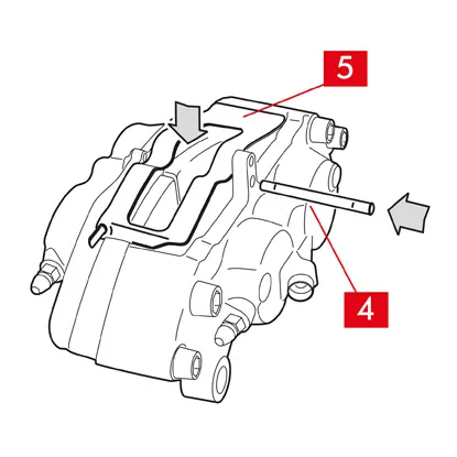
3. Plaats de veren (punt 5) en de pennen (punt 4) terug in de betreffende zittingen in de remklauw en remblokken. De pennen moeten geheel worden ingedreven met een hamer en een pendrijver.
Neem bij de montage van de veren de juiste richting in acht.
4. controleer of de veren correct geplaatst zijn.

5. Voor modellen voorzien van veiligheidssplitpennen (punt 2) moeten deze met een tang teruggeplaatst worden.
6. Controleer of de splitpennen correct geplaatst zijn.
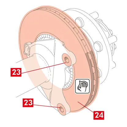
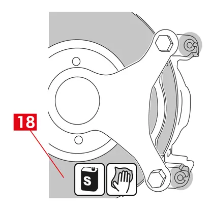
7. Reinig het remvlak (punt 17) van de schijf (punt 18) met gebruik van een ontvetter (bijv. oplosmiddel SE 47).
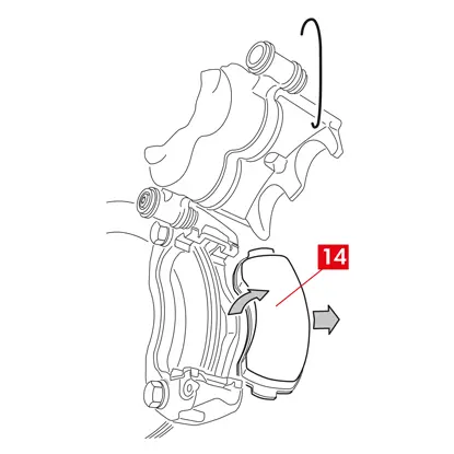
8. Plaats de nieuwe remklauw op de as en plaats de schijf (punt 18) tussen de remblokken.
9. Scherp de bevestigingsschroeven (punt 14) aan met een steeksleutel, naar het door de fabrikant van het voertuig aanbevolen aanhaalmoment.
Gebruik anders ter referentie de volgende aanbevolen aanhaalmomenten:
| Type schroef | M12x1,25 | M12x1,5 | M14x1,5 |
| Aanhaalmoment | 115 Nm | 125 Nm | 180 Nm |
10. Sluit de kabel van de slijtage-indicator, indien aanwezig, weer aan op de klem in het voertuig en maak hem vast in eventuele bevestigingen op het chassis en de remklauw.
11. Sluit de toevoerleiding van remvloeistof (punt 13) weer aan.
12. Verwijder de eerder in de passagiersruimte aangebrachte afstandshouder, waardoor het rempedaal wordt vrijgegeven en dus het circuit weer wordt geopend.
13. Voor achterste remklauwen van type C (met parkeermechanisme) moet de kabel voor parkeerregeling (punt 11) weer worden aangesloten.
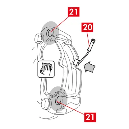
14. Verwijder de vergrendelingspen van de hendel (punt 19).
15. Activeer in het voertuig de parkeerrem. Herhaal het proces meerdere keren, tot de slag van de hendel van het remmechanisme is hersteld naar de minimale waarden.
16. Open de dop van het remvloeistofreservoir.
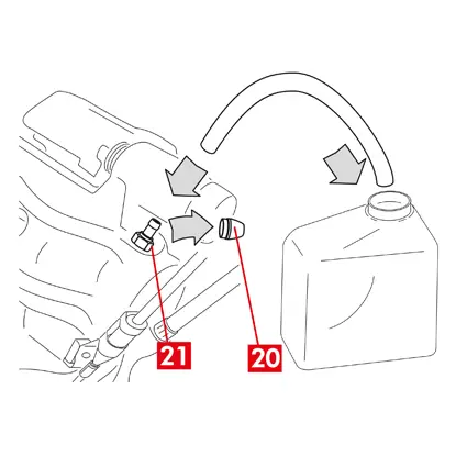
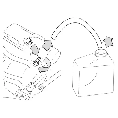
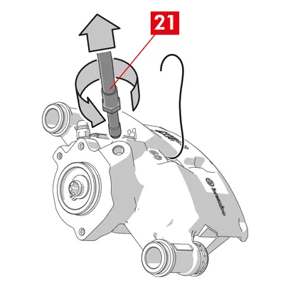
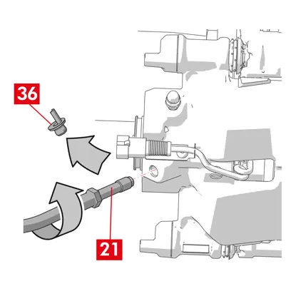
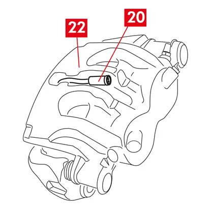
17. Verwijder de beschermende dop (punt 20) en sluit een transparante slang aan op de ontluchtingsplug (punt 21) op de remklauw; het andere uiteinde van de slang moet geplaatst worden in een bak voor het opvangen van eventuele vloeistof.
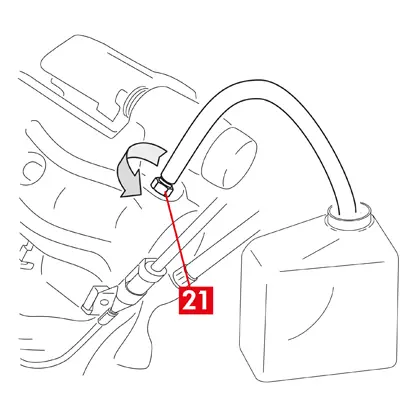
18. Open de ontluchtingsplug (punt 21).
19. Trap het rempedaal herhaaldelijk in, tot de remvloeistof uit de ontluchtingsplug begint te stromen.
20. Houd het rempedaal ingetrapt en sluit de ontluchtingsplug. Laat het pedaal los, wacht enkele seconden en herhaal het proces dan tot er vloeistof zonder luchtbellen naar buiten stroomt en tot de gebruikelijke weerstand en slag van het rempedaal zijn hersteld.
21. Draai de ontluchtingsplug dicht en scherp aan naar het aanhaalmoment aangegeven in de tabel:
| Ontluchtingsplug | M6x1 | M6x1 | M6x1 | M6x1 |
| Aanhaalmoment | 5÷7 Nm | 7÷10 Nm | 17÷20 Nm | 18÷22 Nm |
22. Verwijder de transparante slang en plaats de beschermende dop terug op de ontluchtingsplug.
23. Herhaal de ontluchtingsprocedure voor eventuele andere ontluchtingspluggen.
24. Na het ontluchtingsproces: trek de zuigers volledig terug in de remklauw, met behulp van een geschikt gereedschap (zoals een zuigertang) en vul vervolgens de remvloeistof bij, volgens de aanbevelingen van de fabrikant.
25. Sluit de dop van het remvloeistofreservoir.
26. Pas bij draaiende motor een sterke druk uit op het rempedaal van het voertuig en controleer dat er geen sprake is van vloeistoflekken uit de remklauw of van abnormaal drukverlies in het circuit; controleer ook of de stoplichten gaan branden.
GEVAAR! Als er uit de remklauw vloeistof lekt, herhaal dan alle in dit document beschreven stappen om de oorzaak te bepalen en het probleem te verhelpen.
27. In geval van remklauwen met een ingebouwde parkeerrem moet de klem van de parkeerremkabel worden aangesloten op de betreffende zitting in de remklauw. Trek herhaaldelijk aan de parkeerrem in de passagiersruimte en laat hem vrij.
28. Plaats het wiel terug.
29. Nieuwe remblokken moeten worden ingereden; volg de aanwijzingen verstrekt bij de vervangende remblokken.
Hier volgen de instructies voor de vervanging van de remklauwen:
Zwevende remklauwen met centrale veer
Zwevende remklauwen met 2 of 4 zijdelingse veren en restkoppelreducerende veren.
Alle informatie van dit instructieblad is van toepassing op beide soorten remklauwen, tenzij anders aangegeven.
Vervangingsprocedure
Voordat de vervanging wordt gestart, moet gecontroleerd worden of de voor de vervanging gebruikte reserveonderdelen geschikt zijn voor het merk en model van het voertuig.
- Verwijder het wiel
- Noteer de stand van alle gedeeltelijk of volledig gedemonteerde onderdelen, ten behoeve van de correcte terugplaatsing
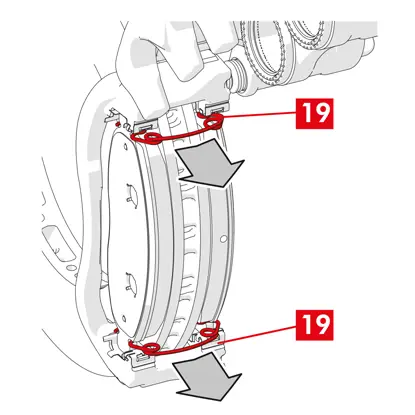
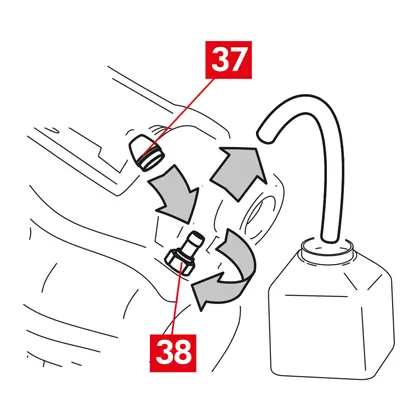
1. Koppel de slijtage-indicator (punt 1), indien aanwezig, los van de klem in het voertuig, door hem los te maken van het plaatje (punt 2) voor de bevestiging op de remklauw en van de eventuele bevestigingen op het chassis.
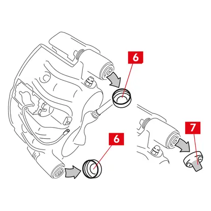
2. Verwijder de beschermende doppen (punt 3) vanaf de geleidebussen.
3. Als de dop een lipje heeft (punt 4), verwijder de dop dan door met uw vingers aan het lipje (punt 4) te trekken.
4. Als de dop is gemaakt van hard plastic (punt 5), gebruik dan een schroevendraaier om hem open te wrikken. Door de verwijdering zal de dop breken.
WAARSCHUWING! De gedemonteerde dop van hard plastic mag niet worden hergebruikt.
OPGELET! De te demonteren geleidebus moet degene zijn die het remklauwlichaam in staat stelt te draaien zonder dat de toevoerleiding van de remvloeistof wordt uitgerekt.
WAARSCHUWING! Er zijn twee soorten geleidebussen:
- met aparte schroef
- met ingebouwde schroef
5. Draai de schroef (punt 6) of de ingebouwde geleidebus (punt 7) los en verwijder ze volledig met een sleutel
WAARSCHUWING! Als er sprake is van remblokken die op de remklauw zijn verkleefd, moeten ze met een schroevendraaier worden losgemaakt.
GEVAAR! Bij de opening van het remklauwlichaam zouden de restkoppelreducerende veren naar buiten kunnen springen.
6. In geval van een niet-ingebouwde geleidebus (punt 8) moet hij uit de remklauwbeugel (punt 9) getrokken worden door hem met een schroevendraaier uit zijn zitting te wrikken.
7. Bij de vervanging van de remklauw op de achterwielen met ophanging en bladveren moeten beide geleidebussen (punt 8) verwijderd worden om het remklauwlichaam (punt 10) volledig van de remklauwbeugel (punt 9) te scheiden.
8. Trek het remklauwlichaam (punt 10) weg van de remklauwbeugel (punt 9) door hem rond de andere geleidebus te draaien, tot de remblokken uit de remklauwbeugel komen. Bevestig het remklauwlichaam met geschikte middelen aan het chassis van het voertuig.
9. Verwijder de remblokken (punt 11) en de veren (punt 12), zonder schade te veroorzaken, zodat u ze weer kunt monteren op de nieuwe remklauw.
10. Gebruik een marker om de draairichting van de schijf aan te geven op de remblokken, om een onjuiste montage ervan te voorkomen.
11. Als ze nog op hun plaats aanwezig zijn, verwijder de restkoppelreducerende veren (punt 13).
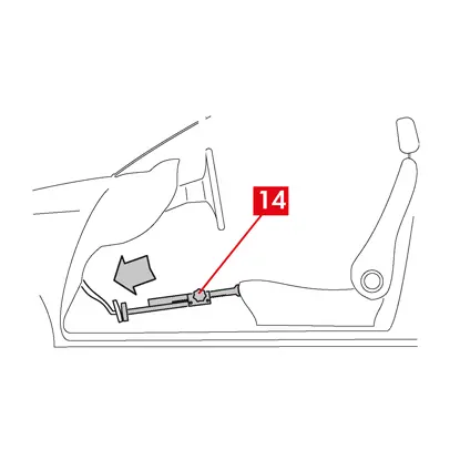
12. Plaats in de passagiersruimte een afstandshouder (punt 14) tussen de stoel en het rempedaal om ervoor te zorgen dat het pedaal gedurende deze handelingen ingetrapt blijft.
WAARSCHUWING! Dit zorgt ervoor dat het hydraulische remcircuit gesloten wordt en het lekken van remvloeistof wordt voorkomen.
OPGELET! Zorg er tijdens alle hieronder beschreven fasen voor dat de remvloeistof niet in contact komt met onderdelen van het voertuig die hierdoor beschadigd kunnen raken, met name de gelakte onderdelen. Per ongeluk gemorste spatten of lekken van remvloeistof moeten onmiddellijk worden opgenomen met een doek/keukenpapier, om vervolgens te reinigen met water.
13. Ontspan de toevoerleiding (punt 15) op de remklauw voldoende om deze volledig met de hand los te kunnen schroeven, omdat op deze manier het lekken van remvloeistof wordt voorkomen.
14. Draai de bevestigingsschroeven (punt 16) los met een steeksleutel en verwijder de remklauwbeugel (punt 9) vanaf de beugel van de naaf.
15. Maak de toevoerleiding (punt 15) volledig los van het remklauwlichaam.
16. Neem eventueel gelekte remvloeistof onmiddellijk op.
17. Houd de toevoerleiding omhoog om het lekken van de vloeistof te voorkomen.
18. In geval van remklauwen met een ingebouwde parkeerrem moet de parkeerremkabel worden losgekoppeld van zijn zitting in de remklauw.
19. Trek de te vervangen remklauw weg.
20. Reinig het remvlak (punt 17) van de schijf met gebruik van een ontvetter (bijv. oplosmiddel SE47).
Montageprocedure remklauw
OPGELET! De beschermende dop van de vloeistofinlaatopening op de nieuwe remklauw mag niet verwijderd worden tot u de toevoerleiding erop aangesloten hebt.
Voorafgaand aan de montage van de nieuwe remklauw moeten de bussen en stofkappen met gebruik van het bijgeleverde vet gesmeerd worden.
WAARSCHUWING! EUH210 - Veiligheidsinformatieblad verkrijgbaar op verzoek.
WAARSCHUWING! EUH208 - Bevat N-gealkyleerde benzotriazool. Kan een allergische reactie veroorzaken.
1. Verwijder de beschermende doppen vanaf de bussen, indien aanwezig.
2. Draai de schroeven of de geleidebussen met ingebouwde schroef los.
3. In geval van aparte schroeven moeten deze volledig worden uitgenomen.
4. Trek het remklauwlichaam weg van de remklauwsteun.
WAARSCHUWING! Om de beschadiging van de stofkappen te voorkomen, moeten de bussen aan de zijkant van de kap worden verwijderd.
5. Verwijder de kappen.
6. Reinig alle te monteren onderdelen, de zittingen van de bussen en de zittingen van de kappen grondig met geschikte producten (bijv. een vochtige doek).
7. Reinig de montagevlakken op de beugel van de naaf.
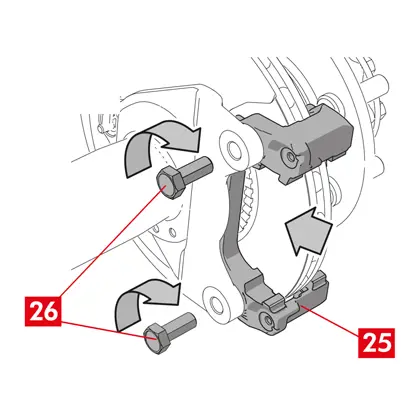
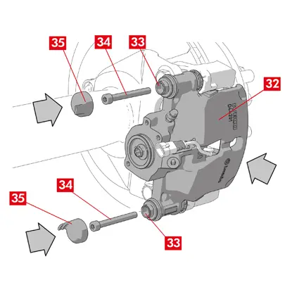
8. Plaats de nieuwe remklauwbeugel (punt 18) door deze in de schijf te plaatsen.
9. Plaats de twee bevestigingsbouten (punten 19 en 20) en draai ze enigszins aan.
10. Scherp de bevestigingsbout op de ingangszijde van de schijf (punt 19) (in vooruitversnelling) aan naar het door de fabrikant van het voertuig aanbevolen aanhaalmoment.
11. Scherp de tweede bevestigingsbout (punt 20) op de uitgangszijde van de schijf aan naar het door de fabrikant van het voertuig aanbevolen aanhaalmoment.
Gebruik ter referentie de volgende aanbevolen aanhaalmomenten:
| Type schroef | Aanhaalmoment |
| M12x1,25 | 115 Nm |
| M12x1,5 | 125 Nm |
| M14x1,5 | 180 Nm |
| M16x1,5 | 210 Nm |
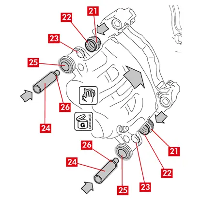
12. Vet het inwendige oppervlak van de kappen (punt 21) en het contactprofiel (punt 22) met het remklauwlichaam gelijkmatig in.
13. Plaats de kappen (punt 21) in de zittingen (punt 23) op het remklauwlichaam.
OPGELET! Gebruik uw vinger en controleer of de kap correct in het remklauwlichaam is aangebracht.
14. Vet het uitwendige oppervlak van de bussen (punt 24) en hun zittingen (punt 25) in het remklauwlichaam in, steek de bussen in het remklauwlichaam, vanaf de zijde tegenover de kap.
15. Duw de bussen (punt 24) aan tot de kappen (punt 21) in hun zittingen (punt 26) zijn aangebracht.
16. Verwijder eventueel overtollig vet.
17. Monteer het remklauwlichaam op de remklauwbeugel door het vast te draaien op de schroef of de ingebouwde bus aan de uitgangszijde van de schijf (in vooruitversnelling).
18. Trek het remklauwlichaam (punt 27) weg van de remklauwbeugel (punt 18) door hem rond de geleidebus te draaien, tot de remblokken in de remklauwbeugel worden geplaatst. Bevestig het remklauwlichaam met geschikte middelen aan het chassis van het voertuig.
OPGELET! Gebruik de zitting van de geleidebus niet als een bevestigingspunt.
De remblokken monteren
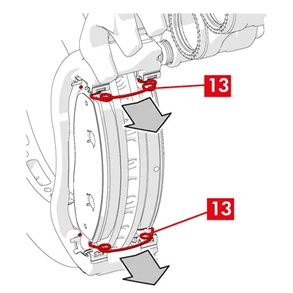
1. Monteer, daar waar voorzien, de zijdelingse veren (punt 12) in de remklauwbeugel en oefen daarvoor de juiste hoeveelheid druk uit om ze stevig te bevestigen.
2. In geval van remklauwen met vier veren moeten de veren altijd gemonteerd worden met de vleugels naar de buitenkant van de remklauwbeugel gericht.
OPGELET! Neem de correcte montagerichting in acht.
WAARSCHUWING! ALS er eventueel remblokken met een zelfklevende zijde zijn, dan moeten nieuwe remblokken gemonteerd worden; volg de bij de vervangende remblokken verstrekte instructies.
OPGELET! Het remblok met een slijtage-indicator moet worden teruggeplaatst op de positie waar hij zich oorspronkelijk voorafgaand aan de demontage bevond.
3. Plaats de remblokken (punt 11) terug in de remklauwbeugel (punt 18); gebruik voor remklauwen van type B een schroevendraaier om de zijdelingse veren (punt 12) open te wrikken.
WAARSCHUWING! Eventuele op de remblokken aangegeven pijlen moeten in de draairichting van de schijf wijzen.
GEVAAR! Remblokken moeten met het frictiemateriaal naar de schijf toe geplaatst worden.
WAARSCHUWING! Eventuele op de remblokken aangegeven pijlen moeten in de draairichting van de schijf wijzen.
GEVAAR! Remblokken moeten met het frictiemateriaal naar de schijf toe geplaatst worden.
4. Leid de kabel van de slijtage-indicator (punt 1) als volgt door het daarvoor bestemde kanaal:
Voor remklauwen type A - in de veer (punt 28).
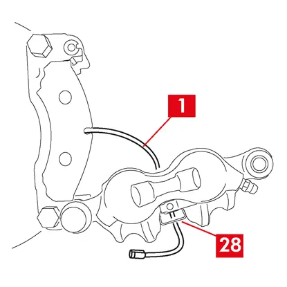
Voor remklauwen type B - in het remklauwlichaam (punt 27).
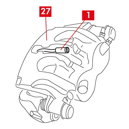
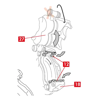
4. Sluit de remklauw voorzichtig, door het remklauwlichaam (punt 27) rond de vastgeschroefde geleidebus te draaien. Als er eventueel remblokken met een zelfklevende zijde zijn, let dan op dat er geen contact ontstaat tussen het remklauwlichaam en het remblok voordat u de montage van het remklauwlichaam hebt voltooid.
OPGELET! Sluit de remklauw voorzichtig en zorg ervoor dat de beschermkappen op de bussen niet beschadigd worden door stoten tegen de remklauwbeugel.
OPGELET! Sluit de remklauw voorzichtig en zorg ervoor dat de beschermkappen op de bussen niet beschadigd worden door stoten tegen de remklauwbeugel.
5. Beweeg het remklauwlichaam (punt 27) naar de remklauwbeugel (punt 18).
6. Plaats de geleidebus (punt 29) terug in de zitting van de remklauwbeugel.
7. Breng, indien aanwezig, een nieuwe schroef (punt 30) aan en schroef deze vast.
8. Bij de vervanging van de remklauw op de achterwielen met ophanging en bladveren moet het remklauwlichaam (punt 27) worden teruggeplaatst op de remklauwbeugel (punt 18), om vervolgens beide geleidebussen (punt 29) terug te plaatsen en, indien aanwezig, twee nieuwe schroeven (punt 30) aan te brengen en aan te scherpen.
9. Als hij nog niet is vastgeschroefd, scherp de bevestigingsschroef van de geleidebus of de ingebouwde geleidebus aan de ingangszijde van de schijf dan aan (in vooruitversnelling). Scherp vervolgens de andere schroef of de andere ingebouwde geleidebus aan naar hetzelfde aanhaalmoment.
10. Scherp aan naar het aanhaalmoment aangegeven in de volgende tabel:
| Type | Aanhaalmoment | |
| Bevestigingsschroef | (M8 – CH6) | 32 ÷ 36 Nm |
| Geleidebus met ingebouwde schroef | (M8 – CH6) | 32 ÷ 36 Nm |
| Geleidebus met ingebouwde schroef | (M10 – CH8) | 65 ÷ 75 Nm |
GEVAAR! Neem de beschreven volgorde voor aanscherpen in acht; gebeurt dit niet, dan kan de goede werking van de remklauw worden aangetast.
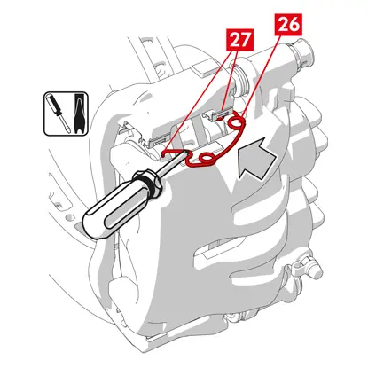
11. In het geval van restkoppelreducerende veren (punt 31) moet de veer onder de plaat (punt 32) van het remblok worden vastgehaakt en moet de onderkant van de plaat op het andere remblok worden gehaakt, met behulp van een schroevendraaier met holle tip.
GEVAAR! Een onjuiste bevestiging van de veer kan ertoe leiden dat de veer open springt.
OPGELET! Neem de correcte montagerichting in acht.
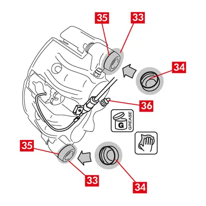
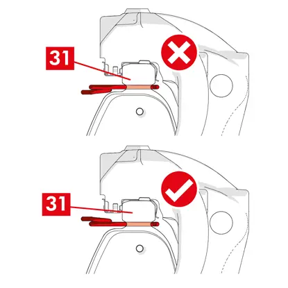
12. Reinig de delen (punt 33) zorgvuldig om ervoor te zorgen dat ze op hun plaats blijven en monteer nieuwe beschermende doppen (punt 34), waarbij hun inwendige oppervlak en de zitting van het remklauwlichaam gesmeerd moeten worden met het vet dat bij de set reserveonderdelen wordt geleverd.
13. Draai de beschermende dop (punt 34) zo dat hij volledig aan de zitting (punt 35) hecht.
14. Sluit de slijtage-indicator, indien aanwezig, weer aan op de klem in het voertuig, door hem met een lichte druk te bevestigen op het plaatje aanwezig op de remklauw en in de eventuele bevestigingen op het chassis.
15. Verwijder de beschermende dop vanaf de inlaatopening van de remvloeistof (punt 36).
16. Sluit de toevoerleiding van remvloeistof weer aan.
17. Verwijder de eerder in de passagiersruimte aangebrachte afstandshouder, waardoor het rempedaal wordt vrijgegeven en dus het hydraulische circuit weer wordt geopend.
18. Open de dop van het remvloeistofreservoir.
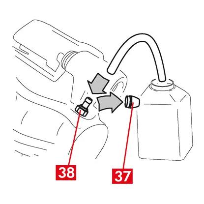
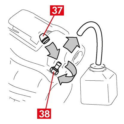
19. Verwijder de beschermende dop (punt 37) en sluit een transparante slang aan op de ontluchtingsplug (punt 38) op de remklauw; het andere uiteinde van de slang moet geplaatst worden in een bak voor het opvangen van eventuele vloeistof.
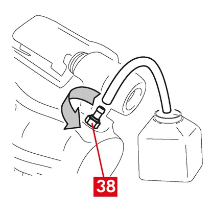
20. Open de ontluchtingsplug (punt 38).
21. Trap het rempedaal herhaaldelijk in, tot de remvloeistof uit de ontluchtingsplug begint te stromen.
22. Houd het rempedaal ingetrapt en sluit de ontluchtingsplug. Laat het pedaal los, wacht enkele seconden en herhaal het proces dan tot er vloeistof zonder luchtbellen naar buiten stroomt en tot de gebruikelijke weerstand en slag van het rempedaal zijn hersteld.
23. Draai de ontluchtingsplug dicht en scherp aan naar het aanhaalmoment aangegeven in de tabel:
| Ontluchtingsplug | M6x1 | M8x1,25 | M10x1 | M12x1 |
| Aanhaalmoment | 5÷7 Nm | 7÷10 Nm | 17÷20 Nm | 18÷22 Nm |
24. Verwijder de transparante slang en plaats de beschermende dop terug op de ontluchtingsplug.
25. Herhaal de ontluchtingsprocedure voor eventuele andere ontluchtingspluggen.
26. Na het ontluchtingsproces: trek de zuigers volledig terug in de remklauw, met behulp van een geschikt gereedschap (zoals een zuigertang) en vul vervolgens de remvloeistof bij, volgens de aanbevelingen van de fabrikant.
27. Sluit de dop van het remvloeistofreservoir.
28. Pas bij draaiende motor een sterke druk uit op het rempedaal van het voertuig en controleer dat er geen sprake is van vloeistoflekken uit de remklauw of van abnormaal drukverlies in het circuit; controleer ook of de stoplichten gaan branden.
GEVAAR! Als er uit de remklauw vloeistof lekt, herhaal dan alle in dit document beschreven stappen om de oorzaak te bepalen en het probleem te verhelpen.
29. In geval van remklauwen met een ingebouwde parkeerrem moet de klem van de parkeerremkabel worden aangesloten op de betreffende zitting in de remklauw.
30. Trek herhaaldelijk aan de parkeerrem in de passagiersruimte en laat hem vrij.
31. Plaats het wiel terug.
32. Nieuwe remblokken moeten worden ingereden; volg de aanwijzingen verstrekt bij de vervangende remblokken.
Hier volgen de instructies voor de vervanging van componenten voor zwevende remklauwen van lichte bedrijfsvoertuigen (type ECS53 en ECS60) met ingebouwd elektrisch parkeerremmechanisme:
1. Actuatorunit
2. Remblokken
3. Lichaam remklauw (zonder remblokken en remklauwbeugel)
4. Remklauwbeugel
2. Remblokken
3. Lichaam remklauw (zonder remblokken en remklauwbeugel)
4. Remklauwbeugel
WAARSCHUWING! Lees dit document voordat u de in de verpakking aanwezige reserveonderdelen vervangt. Verricht uitsluitend die stappen die vereist zijn voor de vervanging van het reserveonderdeel of de delen aanwezig in de verpakking.
Vervangingsprocedure
Voordat de vervanging wordt gestart, moet gecontroleerd worden of de voor de vervanging gebruikte reserveonderdelen geschikt zijn voor het merk en model van het voertuig.
WAARSCHUWING! In het geval van elektrische storingen moet de actuatorunit worden gedemonteerd en de zuiger worden teruggetrokken door de torxschroef met een geschikte sleutel rechtsom te draaien.
- Noteer de stand van alle gedeeltelijk of volledig gedemonteerde onderdelen, ten behoeve van de correcte terugplaatsing.
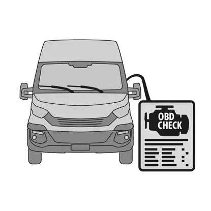
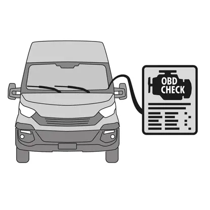
1. Sluit het diagnose-instrument (On Board Diagnosis - OBD) aan op het voertuig en plaats het in de procedure onderhoudsmodus zoals beschreven door de fabrikant van het voertuig.
OPGELET! Controleer of het reserveonderdeel compatibel is met de software van het voertuig.
2. Verwijder het wiel.
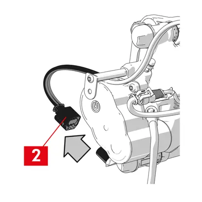
3. Maak de voedingskabel van de actuatorunit los van de kabelwartel.
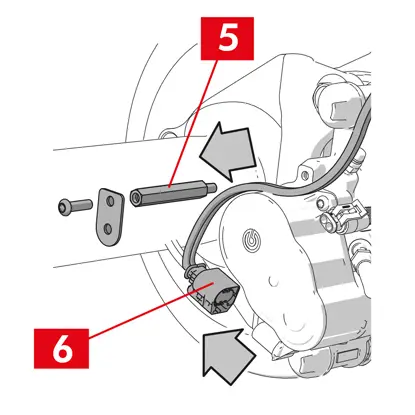
4. Voor remklauw type ECS60 moet de kabelwartel (punt 5) worden losgedraaid en verwijderd.
5. Koppel de voedingskabel (punt 6) los van de actuatorunit.
WAARSCHUWING! De connector is mogelijk voorzien van een veiligheidsvergrendeling.
WAARSCHUWING! De connector is mogelijk voorzien van een veiligheidsvergrendeling.
Demontage actuatorunit
WAARSCHUWING! Ga alleen verder met de demontage van de actuatorunit als er een apart reserveonderdeel beschikbaar is.
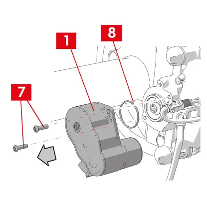
1. Draai de bevestigingsschroeven (punt 7) los van de actuatorunit (punt 1).
2. Verwijder de actuatorunit (punt 1).
3. Verwijder de afdichting (punt 8).
Demontage remblokken
OPGELET! Zorg ervoor dat onderdelen die u wilt hergebruiken niet beschadigd worden.
GEVAAR! Voorkom dat de toevoerleiding van remvloeistof wordt uitgerekt.
GEVAAR! Voorkom dat de toevoerleiding van remvloeistof wordt uitgerekt.
1. Koppel de slijtage-indicator (punt 9), indien aanwezig, los van de klem in het voertuig, door hem los te maken van het plaatje voor de bevestiging op de remklauw en van de eventuele bevestigingen op het chassis.
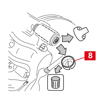
2. Verwijder de beschermende dop (punt 10) vanaf de secundaire bus (omwenteling vooruitversnelling uitgangszijde schijf).
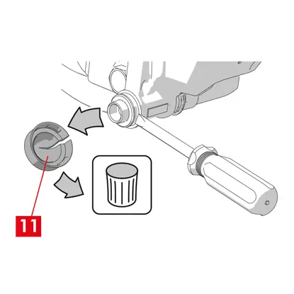
3. Als de dop is gemaakt van hard plastic (punt 11), gebruik dan een schroevendraaier om hem open te wrikken. Door de verwijdering zal de dop breken.
WAARSCHUWING! De gedemonteerde dop van hard plastic mag niet worden hergebruikt.
4. Draai de secundaire schroef (punt 12) los en verwijder hem.
5. Gebruik voor remklauw type ECS60 een schroevendraaier om de bus uit de groef te wrikken en hem uit de remklauwbeugel los te maken.
6. Verwijder de beschermende dop (punt 14) vanaf de primare bus (omwenteling vooruitversnelling ingangszijde schijf).
7. Draai de primaire schroef (punt 15) volledig los en verwijder hem.
WAARSCHUWING! Gebruik een schroevendraaier om de geleidebussen uit de groeven te wrikken.
8. Neem de primaire geleidebus (punt 16) voldoende ver uit om hem los te kunnen maken van de remklauwbeugel.
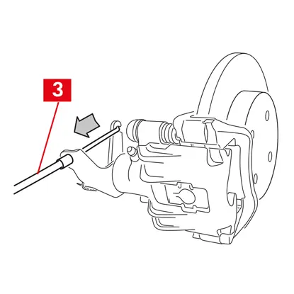
9. Trek het remklauwlichaam (punt 3) weg van de remklauwbeugel (punt 4) en let op dat de toevoerleiding van de remvloeistof niet wordt uitgerekt.
10. Bevestig het remklauwlichaam met geschikte middelen aan het chassis van het voertuig.
OPGELET! Gebruik de zitting van de bus niet als een bevestigingspunt
11. Verwijder de remblokken (punt 17) en de veren (punt 18), zonder schade te veroorzaken, zodat u ze weer kunt monteren op de nieuwe remklauw.
12. Als ze nog op hun plaats aanwezig zijn, verwijder de restkoppelreducerende veren (punt 19).
WAARSCHUWING! Markeer de remblokken, voor hun correcte terugplaatsing, met enkele pijlen (indien niet aanwezig) om de draairichting van de schijf aan te geven.
Demontage lichaam remklauw
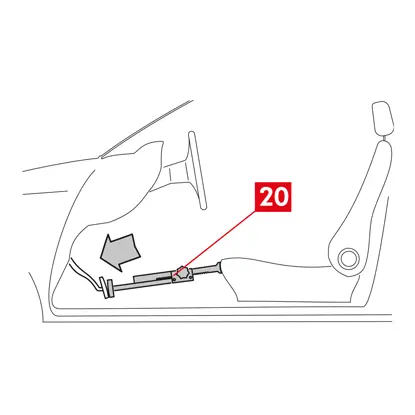
1. Plaats in de passagiersruimte een afstandshouder (punt 20) tussen de stoel en het rempedaal om ervoor te zorgen dat het pedaal gedurende deze handelingen ingetrapt blijft.
WAARSCHUWING! Dit zorgt ervoor dat het hydraulische remcircuit gesloten wordt en het lekken van remvloeistof wordt voorkomen.
OPGELET! Zorg er tijdens alle hieronder beschreven fasen voor dat de remvloeistof niet in contact komt met onderdelen van het voertuig die hierdoor beschadigd kunnen raken, met name de gelakte onderdelen. Per ongeluk gemorste spatten of lekken van remvloeistof moeten onmiddellijk worden opgenomen met een doek/keukenpapier, om vervolgens te reinigen met water.
2. Ontspan de toevoerleiding (punt 21) op de remklauw voldoende om deze volledig met de hand los te kunnen schroeven, omdat op deze manier het lekken van remvloeistof wordt voorkomen.
3. Maak de toevoerleiding (punt 21) volledig los van het remklauwlichaam.
4. Neem eventueel gelekte remvloeistof onmiddellijk op.
5. Houd de toevoerleiding omhoog om het lekken van de vloeistof te voorkomen.
6. Trek het remklauwlichaam (punt 3) weg.
Demontage remklauwbeugel
OPGELET! Houd de remklauwbeugel tijdens de demontage goed vast om te voorkomen dat hij per ongeluk valt.
1. Draai de bevestigingsschroeven (punt 22) los.
2. Verwijder de remklauwbeugel (punt 4) vanaf de beugel van de naaf.
Montageprocedure
Monteer de nieuwe reserveonderdelen.
1. Reinig alle te monteren onderdelen (ongeacht het feit of ze nieuw zijn of eerder verwijderd werden), de zittingen van de bussen en de zittingen van de veren grondig met geschikte producten (bijv. een vochtige doek).
GEVAAR! Controleer of de onderdelen intact zijn en vervang beschadigde onderdelen door nieuwe exemplaren.
2. Reinig de montagevlakken (punt 23) op de beugel van de naaf.
3. Reinig het remvlak (punt 24) van de schijf met gebruik van een ontvetter (bijv. oplosmiddel SE47).
Montage remklauwbeugel
1. Plaats de nieuwe remklauwbeugel (punt 25) op de beugel van de naaf.
2. Plaats de bevestigingsschroeven (punt 26) en scherp ze aan naar het aanhaalmoment aanbevolen door de fabrikant van het voertuig.
Montage remblokken en lichaam remklauw
1. Plaats de veren (punt 27) op de juiste manier terug in hun zittingen.
2. Voor remklauw type ECS52 met vier veren moeten de veren altijd gemonteerd worden met de vleugels (punt 28) naar de buitenkant van de remklauwbeugel gericht.
WAARSCHUWING! ALS er eventueel remblokken met een zelfklevende zijde zijn, dan moeten nieuwe remblokken gemonteerd worden; volg de bij de vervangende remblokken verstrekte instructies.
OPGELET! Het remblok met een slijtage-indicator moet worden teruggeplaatst op de positie waar hij zich oorspronkelijk voorafgaand aan de demontage bevond.
GEVAAR! Remblokken moeten met het frictiemateriaal naar de schijf toe geplaatst worden.
3. Plaats de remblokken (punt 29) terug in de remklauwbeugel (punt 25); gebruik een schroevendraaier om de zijdelingse veren (punt 27) open te wrikken.
4. In het geval van restkoppelreducerende veren (punt 30) moet de veer onder de plaat (punt 31) van het remblok worden vastgehaakt en moet de onderkant van de plaat op het andere remblok worden gehaakt, met behulp van een schroevendraaier met holle tip.
GEVAAR! Een onjuiste bevestiging van de veer kan ertoe leiden dat de veer open springt.
GEVAAR! Een onjuiste bevestiging van de veer kan ertoe leiden dat de veer open springt.
OPGELET! Neem de correcte montagerichting in acht.
OPGELET! Als het remklauwlichaam nieuw is, mag de beschermende dop van de vloeistofinlaatopening op de nieuwe remklauw niet verwijderd worden tot u de toevoerleiding erop aangesloten hebt.
6. Plaats het remklauwlichaam (punt 32) door het in de schijf te steken, zo dat de geleidebussen overeenkomen met de gaten op de remklauwbeugel.
OPGELET! Beschadig de kappen niet.
7. Duw de geleidebussen (punt 33) in hun zittingen op de remklauwbeugel.
8. Breng de schroeven (punt 34) aan en scherp ze aan naar een aanhaalmoment van 32 ÷ 36 Nm.
9. Plaats de doppen (punt 35).
OPGELET! Voordat de beschermende dop wordt verwijderd, moet het vulpunt zo hoog mogelijk geplaatst worden om ervoor te zorgen dat de remvloeistof niet uit de remklauw lekt.
10. Sluit de kabel van de slijtage-indicator, indien aanwezig, weer aan op de klem in het voertuig, door hem met een lichte druk te bevestigen op het plaatje op de remklauw, indien aanwezig, en in de eventuele bevestigingen op het chassis.
Aansluiting toevoerleiding remvloeistof
1. Verwijder de beschermende dop (punt 36) vanaf de inlaatopening van de remvloeistof.
2. Sluit de toevoerleiding van remvloeistof (punt 21) weer aan.
3. Verwijder de eerder in de passagiersruimte aangebrachte afstandshouder, waardoor het rempedaal wordt vrijgegeven en dus het circuit weer wordt geopend.
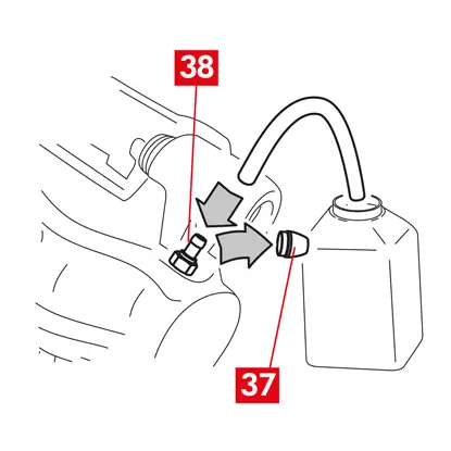
4. Verwijder de beschermende dop (punt 37) vanaf de ontluchtingsplug (punt 38).
5. Sluit een transparante slang aan op de ontluchtingsplug (punt 38) op de remklauw; het andere uiteinde van de slang moet geplaatst worden in een bak voor het opvangen van eventuele vloeistof.
6. Open de ontluchtingsplug (punt 38).
7. Trap het rempedaal herhaaldelijk in, tot de remvloeistof uit de ontluchtingsplug begint te stromen.
8. Houd het rempedaal ingetrapt en sluit de ontluchtingsplug. Laat het pedaal los, wacht enkele seconden en herhaal het proces dan tot er vloeistof zonder luchtbellen naar buiten stroomt en tot de gebruikelijke weerstand en slag van het rempedaal zijn hersteld.
9. Draai de ontluchtingsplug (punt 38) dicht en scherp aan naar het aanhaalmoment aangegeven in de volgende tabel:
| Type ontluchtingsplug | M10x1 |
| Aanhaalmoment | 12÷16 Nm |
10. Verwijder de transparante slang.
11. Herhaal de ontluchtingsprocedure voor eventuele andere ontluchtingspluggen.
12. Plaats de beschermende dop (punt 37) terug.
13. Na het ontluchtingsproces: trek de zuigers volledig terug in de remklauw, met behulp van een geschikt gereedschap (zoals een zuigertang) en vul vervolgens de remvloeistof bij, volgens de aanbevelingen van de fabrikant.
14. Pas bij draaiende motor een sterke druk uit op het rempedaal van het voertuig en controleer dat er geen sprake is van vloeistoflekken uit de remklauw of van abnormaal drukverlies in het circuit; controleer ook of de stoplichten gaan branden.
GEVAAR! Als er uit de remklauw vloeistof lekt, herhaal dan alle in dit document beschreven stappen om de oorzaak te bepalen en het probleem te verhelpen.
Montage actuatorunit
WAARSCHUWING! De actuatorunit is mogelijk al gemonteerd op het remklauwlichaam.
Monteer de nieuwe reserveonderdelen.
- Reinig alle eerder verwijderde onderdelen voordat u ze terugplaatst.
OPGELET! Gebruik altijd nieuwe schroeven en schroefdraadborging. Breng altijd een nieuwe afdichting aan.
GEVAAR! Controleer of de onderdelen intact zijn en vervang beschadigde onderdelen door nieuwe exemplaren
1. Reinig het contactoppervlak op de remklauw en op de actuatorunit.
2. Verwijder eventuele resten van schroefdraadborging vanaf de schroefdraad van de zittingen van de schroeven.
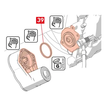
3. Reinig en smeer de afdichting (punt 39) met het bijgeleverde vet.
4. Smeer de inwendige diameter van de koppeling van de actuatorunit in met het bijgeleverde vet.
WAARSCHUWING! EUH210 - Veiligheidsinformatieblad verkrijgbaar op verzoek.
WAARSCHUWING! EUH208 - Bevat N-gealkyleerde benzotriazool. Kan een allergische reactie veroorzaken.
5. Plaats de afdichting (punt 39) in zijn zitting (punt 40) op het remklauwlichaam.
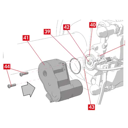
6. Monteer de actuatorunit (punt 41) op de torxschroef (punt 42) op het remklauwlichaam.
7. Draai de actuatorunit (punt 41) zo dat de gaten (punt 43) van de bevestigingsschroeven (punt 44) overeenkomen met hun oorspronkelijke montagepositie.
OPGELET! Vermijd dat de afdichting (punt 39) bekneld raakt tijdens de montage van de actuatorunit op het remklauwlichaam.
8. Breng de bevestigingsschroeven (punt 44) aan en scherp ze aan naar een aanhaalmoment van 7 ÷ 10 Nm.
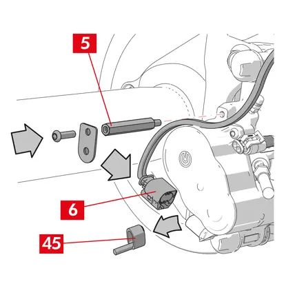
9. Verwijder de beschermende dop (punt 45), indien aanwezig, en sluit de voedingskabel (punt 6) aan.
10. Schroef, indien eerder verwijderd, de kabelwartel (punt 5) vast.
11. Bevestig de voedingskabel (punt 6) van de actuatorunit op de kabelwartel (punt 5).
Laatste fasen
1. Plaats het wiel terug.
2. Verricht de resetprocedure (controle montage).
3. Reset de tellers, indien nodig, (reset interne tellers) zoals voorgeschreven door de fabrikant van het voertuig.
4. Indien voorgeschreven door de fabrikant van het voertuig, moeten de remblokken worden ingereden.
5. Koppel het diagnose-instrument los. (On Board Diagnosis – OBD).
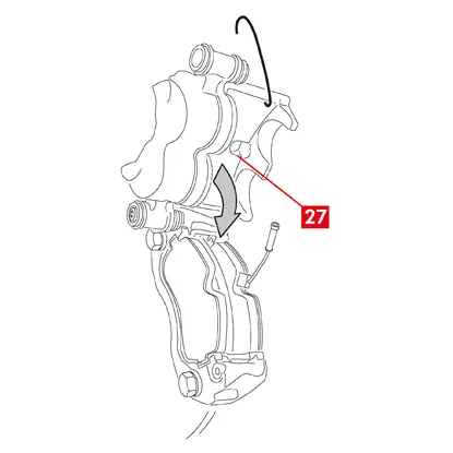
Hier volgen de instructies voor de vervanging van het remklauwlichaam voor zwevende remklauwen met 2 of 4 zijdelingse veren en met restkoppelreducerende veren.
Wanneer alleen de bevestigingsschroeven worden vervangen, moet alleen naar de relevante delen worden verwezen.
Vervangingsprocedure
Voordat de vervanging wordt gestart, moet gecontroleerd worden of de voor de vervanging gebruikte reserveonderdelen geschikt zijn voor het merk en model van het voertuig.
- Noteer de stand van alle gedeeltelijk of volledig gedemonteerde onderdelen, ten behoeve van de correcte terugplaatsing.
- Verwijder het wiel.
Voor ECS-remklauwen
WAARSCHUWING! In het geval van elektrische storingen moet de actuatorunit (punt 5) worden gedemonteerd en de zuiger worden teruggetrokken door de torxschroef met een geschikte sleutel rechtsom te draaien

1. Sluit het diagnose-instrument (On Board Diagnosis - OBD) aan op het voertuig en plaats het in de procedure onderhoudsmodus zoals beschreven door de fabrikant van het voertuig.
OPGELET! Zonder deze handeling kan de zuiger niet worden teruggetrokken met een zuigertang of een ander geschikt gereedschap.
OPGELET! Controleer of het reserveonderdeel compatibel is met de software van het voertuig.
2. Koppel de voedingskabel (punt 2) los van de actuatorunit.
WAARSCHUWING! De connector is mogelijk voorzien van een veiligheidsvergrendeling.
Voor alle soorten remklauwen
1. Voor remklauwen met een parkeerrem: koppel de besturingskabel (punt 3) los van de remklauw.
2. Koppel de slijtage-indicator (punt 4), indien aanwezig, los van de klem in het voertuig, door hem los te maken van het plaatje (punt 5) voor de bevestiging op de remklauw en van de eventuele bevestigingen op het chassis.
3. Verwijder de beschermende doppen (punt 6) vanaf de geleidebussen.
4. Als de dop een lipje heeft (punt 7), verwijder de dop dan door met uw vingers aan het lipje (punt 7) te trekken.
5. Als de dop is gemaakt van hard plastic (punt 8), gebruik dan een schroevendraaier om hem open te wrikken. Door de verwijdering zal de dop breken.
WAARSCHUWING! De gedemonteerde dop van hard plastic mag niet worden hergebruikt.
OPGELET! De te demonteren geleidebus moet degene zijn die het remklauwlichaam in staat stelt te draaien zonder dat de toevoerleiding van de remvloeistof wordt uitgerekt.
WAARSCHUWING! Er zijn twee soorten geleidebussen: met aparte schroef en met ingebouwde schroef.
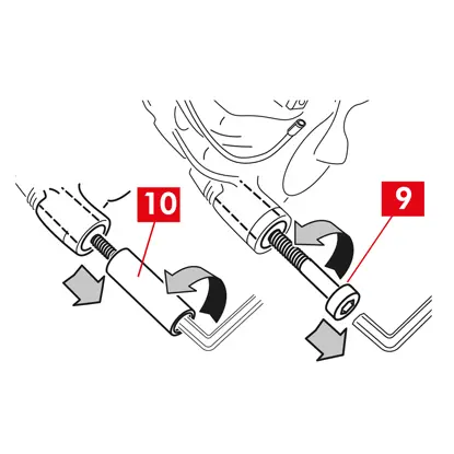
6. Draai de schroef (punt 9) of de ingebouwde geleidebus (punt 10) los en verwijder ze met een sleutel.
7. In geval van een niet-ingebouwde geleidebus (punt 11) moet hij uit de remklauwbeugel (punt 12) getrokken worden door hem met een schroevendraaier uit zijn zitting te wrikken.
8. Bij de vervanging van de remklauw op de achterwielen met ophanging en bladveren moeten beide geleidebussen (punt 11) verwijderd worden om het remklauwlichaam (punt 13) volledig van de remklauwbeugel (punt 12) te scheiden.
WAARSCHUWING! Als er sprake is van remblokken die op de remklauw zijn verkleefd, moeten ze met een schroevendraaier worden losgemaakt en moet worden opgelet dat de rubberen delen van de remklauw niet beschadigd worden.
GEVAAR! Bij de opening van het remklauwlichaam zouden de restkoppelreducerende veren naar buiten kunnen springen.
9. Trek het remklauwlichaam (punt 13) weg van de remklauwbeugel (punt 12) door hem rond de andere geleidebus te draaien, tot de remblokken (punt 14) uit de remklauwbeugel komen. Bevestig het remklauwlichaam met geschikte middelen aan het chassis van het voertuig. Gebruik de zitting van de bus niet als een bevestigingspunt.
11. Verwijder de remblokken (punt 14) zonder schade te veroorzaken.
12. Gebruik een marker om de draairichting van de schijf aan te geven op de remblokken, om een onjuiste montage ervan te voorkomen.
14. Als ze nog op hun plaats aanwezig zijn, verwijder de restkoppelreducerende veren (punt 15).
15. Plaats in de passagiersruimte een afstandshouder (punt 16) tussen de stoel en het rempedaal om ervoor te zorgen dat het pedaal gedurende deze handelingen ingetrapt blijft.
WAARSCHUWING! Dit zorgt ervoor dat het hydraulische remcircuit gesloten wordt en het lekken van remvloeistof wordt voorkomen.
OPGELET! Zorg er tijdens alle hieronder beschreven fasen voor dat de remvloeistof niet in contact komt met onderdelen van het voertuig die hierdoor beschadigd kunnen raken, met name de gelakte onderdelen. Per ongeluk gemorste spatten of lekken van remvloeistof moeten onmiddellijk worden opgenomen met een doek/keukenpapier, om vervolgens te reinigen met water.
OPGELET! Zorg er tijdens alle hieronder beschreven fasen voor dat de remvloeistof niet in contact komt met onderdelen van het voertuig die hierdoor beschadigd kunnen raken, met name de gelakte onderdelen. Per ongeluk gemorste spatten of lekken van remvloeistof moeten onmiddellijk worden opgenomen met een doek/keukenpapier, om vervolgens te reinigen met water.
16. Ontspan de toevoerleiding (punt 17) op de remklauw voldoende om deze volledig met de hand los te kunnen schroeven, omdat op deze manier het lekken van remvloeistof wordt voorkomen.
17. Draai de schroef (punt 9) of de ingebouwde geleidebus (punt 10) volledig los en verwijder ze.
18. In geval van een niet-ingebouwde geleidebus (punt 11) moet hij uit de remklauwbeugel (punt 12) getrokken worden door hem met een schroevendraaier uit zijn zitting te wrikken.
19. Trek het remklauwlichaam (punt 13) weg van de remklauwbeugel (punt 12) en let op dat de toevoerleiding van de remvloeistof niet wordt uitgerekt.
20. Maak de toevoerleiding (punt 17) volledig los van het remklauwlichaam.
21. Neem eventueel gelekte remvloeistof onmiddellijk op.
22. Houd de toevoerleiding omhoog om het lekken van de remvloeistof te voorkomen.
23. Trek de te vervangen remklauw weg.
24. In geval van remklauwen met een ingebouwde parkeerrem moet de parkeerremkabel worden losgekoppeld van zijn zitting in de remklauw.
25. Reinig de remvlakken van de schijf met gebruik van een ontvetter (bijv. oplosmiddel SE47).
De remblokken monteren
OPGELET! Als er eventueel remblokken met een zelfklevende zijde zijn, dan moeten nieuwe remblokken gemonteerd worden; volg de bij de vervangende remblokken verstrekte instructies.
1. Controleer of de veren correct geplaatst zijn. In geval van remklauwen met vier veren moeten ervoor gezorgd worden dat de vleugels altijd naar de buitenkant van de remklauwbeugel worden gericht.
OPGELET! Een onjuiste positionering van de veren kan mogelijk letsel veroorzaken.
2. Plaats de remblokken (punt 14) in de remklauwbeugel (punt 12). Gebruik een schroevendraaier om de zijdelingse veren aan te drukken.
WAARSCHUWING! Eventuele op de remblokken aangegeven pijlen moeten in de draairichting van de schijf wijzen.
GEVAAR! Remblokken moeten met het frictiemateriaal naar de schijf toe geplaatst worden.
OPGELET! Het remblok met een slijtage-indicator moet worden teruggeplaatst op de positie waar hij zich oorspronkelijk voorafgaand aan de demontage bevond.
3. Bevestig, indien aanwezig, de klem van de slijtage-indicator (punt 20) op het blok tegenover de zuigers en vervang het indien nodig.
OPGELET! Zorg er bij de bevestiging van de klem van de slijtage-indicator voor dat het meest uitstekende gedeelte naar het frictieoppervlak op het remblok is gericht.
OPGELET! Zorg er bij de bevestiging van de klem van de slijtage-indicator voor dat het meest uitstekende gedeelte naar het frictieoppervlak op het remblok is gericht.
Montage lichaam remklauw
OPGELET! Voor remklauwen met een parkeerrem - wanneer het remklauwlichaam vanaf de remschijf is gedemonteerd en/of de remblokken niet aanwezig zijn, mag de zuiger niet hydraulisch of door middel van de hendel worden bewogen omdat dit de veer kan beschadigen en/of het lekken van remvloeistof kan veroorzaken.
1. Veeg op de remklauwbeugel de montagegebieden (punt 21) met het remklauwlichaam (geleidezittingen) af met een vochtige doek.
OPGELET! Gebruik geen producten die de beschermkappen kunnen beschadigen, zoals nitro-tetrachloorethyleenverdunner, benzine, enz.
2. Reinig het gehele inwendige oppervlak van de kappen, het buitenoppervlak van de geleidebussen en hun zittingen in het remklauwlichaam en smeer ze gelijkmatig in met vet.
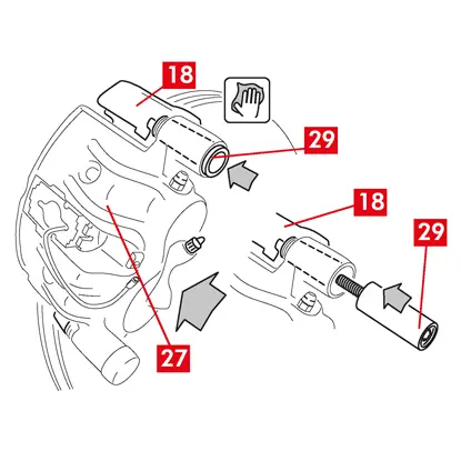
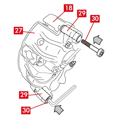
3. Plaats het nieuwe remklauwlichaam (punt 22) en plaats één van de twee geleidebussen (punt 10) in de zitting op de remklauwbeugel (punt 12).
OPGELET! Verwijder de beschermende dop van de inlaatopening van de remvloeistof niet voordat de slang definitief is aangesloten.
OPGELET! Verwijder de beschermende dop van de inlaatopening van de remvloeistof niet voordat de slang definitief is aangesloten.
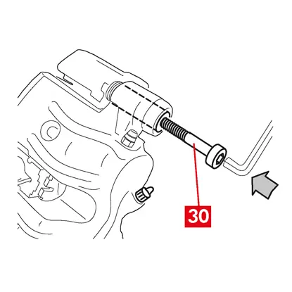
4. In geval van een niet-ingebouwde geleidebus (punt 11) moet een nieuwe schroef (punt 23) gemonteerd en aangescherpt worden.
5. Sluit de remklauw voorzichtig, door het remklauwlichaam (punt 22) rond de gemonteerde geleidebus te draaien.
OPGELET! Sluit de remklauw voorzichtig en zorg ervoor dat de beschermkappen op de bussen niet beschadigd worden door stoten tegen de steun van de remklauw. Vervang de kappen indien nodig.
WAARSCHUWING! Als er eventueel remblokken met een zelfklevende zijde zijn, let dan op dat er geen contact ontstaat tussen het lichaam en het remblok voordat u de montage van het remklauwlichaam hebt voltooid.
6. Leid de sonde van de slijtage-indicator (punt 20) door de daarvoor bestemde opening in het remklauwlichaam (punt 22).
7. Plaats de andere geleidebus (punt 10) terug in de zitting van de remklauwbeugel (punt 12).
8. In geval van een niet-ingebouwde geleidebus (punt 11) moet een nieuwe schroef (punt 24) gemonteerd en aangescherpt worden.
OPGELET! Bij de vervanging van de remklauw op de achterwielen met ophanging en bladveren moet het remklauwlichaam worden teruggeplaatst op de remklauwbeugel, om vervolgens beide geleidebussen terug te plaatsen en twee nieuwe schroeven aan te brengen en aan te scherpen.
9. Scherp de bevestigingsschroef van de geleidebus of de ingebouwde geleidebus (punt 24) aan de ingangszijde van de schijf aan (in vooruitversnelling). Scherp vervolgens de andere schroef of de andere ingebouwde geleidebus (punt 25) aan naar hetzelfde aanhaalmoment.
10. Scherp aan naar het aanhaalmoment aangegeven in de volgende tabel:
| Type | Aanhaalmoment | |
| Bevestigingsschroef | (M8 – CH6) | 32 ÷ 36 Nm |
| Geleidebus met ingebouwde schroef | (M8 – CH6) | 32 ÷ 36 Nm |
| Geleidebus met ingebouwde schroef | (M10 – CH8) | 65 ÷ 75 Nm |
GEVAAR! Neem de beschreven volgorde voor aanscherpen in acht; gebeurt dit niet, dan kan de goede werking van de remklauw worden aangetast.
11. In het geval van restkoppelreducerende veren (punt 26) moet de veer onder de plaat (punt 27) van het remblok worden vastgehaakt en moet de onderkant van de plaat op het andere remblok worden gehaakt, met behulp van een schroevendraaier met holle tip.
GEVAAR! Een onjuiste bevestiging van de veer kan ertoe leiden dat de veer open springt.
OPGELET! Neem de correcte montagerichting in acht.
12. Reinig het onderdeel (punt 28) zorgvuldig om ervoor te zorgen dat het op zijn plaats blijft en monteer nieuwe beschermende doppen (punt 29), waarbij hun inwendige oppervlak en de zitting van het remklauwlichaam gesmeerd moeten worden met het vet dat bij de set reserveonderdelen wordt geleverd.
WAARSCHUWING! EUH210 - Veiligheidsinformatieblad verkrijgbaar op verzoek.
WAARSCHUWING! EUH208 - Bevat N-gealkyleerde benzotriazool. Kan een allergische reactie veroorzaken.
WAARSCHUWING! EUH208 - Bevat N-gealkyleerde benzotriazool. Kan een allergische reactie veroorzaken.
13. Draai de beschermende doppen (punt 29) zo dat ze volledig aan de zitting (punt 30) hechten.
14. Sluit de slijtage-indicator, indien aanwezig, weer aan op de klem in het voertuig, door hem met een lichte druk te bevestigen op het plaatje aanwezig op de remklauw en in de eventuele bevestigingen op het chassis.
15. Verwijder de beschermende dop vanaf de inlaatopening van de remvloeistof.
16. Sluit de toevoerleiding van remvloeistof weer aan.
17. Verwijder de eerder in de passagiersruimte aangebrachte afstandshouder, waardoor het rempedaal wordt vrijgegeven en dus het circuit weer wordt geopend.
Voor remklauwen met een parkeerrem
OPGELET! Voordat de zuiger met de remblokken wordt gemonteerd, moet gecontroleerd worden of de remklauwbeugel, de remblokken en de schijf aanwezig zijn.
- Gebruik de hendel om de zuiger met de remblokken te monteren.
OPGELET! De hydraulische werking is alleen toegestaan wanneer de zuiger zich op minder dan 1 mm van de remblokken bevindt.
Voor alle soorten remklauwen
1. Sluit een transparante slang aan op de ontluchtingsplug (punt 31) op de remklauw; het andere uiteinde van de slang moet geplaatst worden in een bak voor het opvangen van eventuele vloeistof.
2. Open de ontluchtingsplug (punt 31).
3. Trap het rempedaal herhaaldelijk in, tot de remvloeistof uit de ontluchtingsplug begint te stromen.
4. Houd het rempedaal ingetrapt en sluit de ontluchtingsplug. Laat het pedaal los, wacht enkele seconden en herhaal het proces dan tot er vloeistof zonder luchtbellen naar buiten stroomt en tot de gebruikelijke weerstand en slag van het rempedaal zijn hersteld.
5. Draai de ontluchtingsplug (punt 31) dicht en scherp aan naar het aanhaalmoment aangegeven in de volgende tabel:
| Ontluchtingsplug | M6x1 | M8x1,25 | M10x1 | M12x1 |
| Aanhaalmoment | 5÷7 Nm | 7÷10 Nm | 17÷20 Nm | 18÷22 Nm |

6. Verwijder de transparante slang.
7. Herhaal de ontluchtingsprocedure voor eventuele andere ontluchtingspluggen.
8. Na het ontluchtingsproces: trek de zuigers volledig terug in de remklauw, met behulp van een geschikt gereedschap (zoals een zuigertang) en vul vervolgens de remvloeistof bij, volgens de aanbevelingen van de fabrikant.
9. Sluit de dop van het remvloeistofreservoir.
10. Pas bij draaiende motor een sterke druk uit op het rempedaal van het voertuig en controleer dat er geen sprake is van vloeistoflekken uit de remklauw of van abnormaal drukverlies in het circuit; controleer ook of de stoplichten gaan branden.
GEVAAR! Als er uit de remklauw vloeistof lekt, herhaal dan alle in dit document beschreven stappen om de oorzaak te bepalen en het probleem te verhelpen.
Voor remklauwen met een parkeerrem
- Sluit de slijtage-indicator, indien aanwezig, weer aan op de klem in het voertuig, door hem met een lichte druk te bevestigen op het plaatje aanwezig op de remklauw en in de eventuele bevestigingen op het chassis.
- Herstel de correcte spanning naar de besturingskabel.
- Bedien de parkeerremhendel in de cabine van het voertuig herhaaldelijk, tot de normale slag is hersteld.
Voor ECS-remklauwen
1. Verwijder de beschermende dop (indien aanwezig) en sluit de voedingskabel (punt 2) aan.
2. Verricht de resetprocedure (controle montage).
3. Reset de tellers, indien nodig, (reset interne tellers) zoals voorgeschreven door de fabrikant van het voertuig.
4. Indien voorgeschreven door de fabrikant van het voertuig, moeten de remblokken worden ingereden.
5. Koppel het diagnose-instrument los (On Board Diagnosis - OBD).
Voor alle soorten remklauwen
1. Plaats het wiel terug.
2. Nieuwe remblokken moeten worden ingereden; volg de aanwijzingen verstrekt bij de vervangende remblokken.
2. Nieuwe remblokken moeten worden ingereden; volg de aanwijzingen verstrekt bij de vervangende remblokken.
Garantiebeperkingen
Deze garantie dekt alle conformiteitsgebreken die zich binnen twee jaar na de levering van de goederen voordoen. De consument moet de verkoper binnen twee maanden na de datum van ontdekking informeren over het conformiteitsgebrek, onverminderd het feit dat de verjaringstermijn voor het ondernemen van actie gericht op het aanvragen van herstel van het gebrek gelijk is aan zesentwintig maanden na de levering van de goederen. In geval van een conformiteitsgebrek heeft de gebruiker het recht op reparatie of vervanging van de goederen, of een passende prijsvermindering of de beëindiging van het contract, zoals bepaald door art. 130 van het Consumentenrecht, indien van toepassing.
Deze garantie vormt de enige garantie die met betrekking tot dit product wordt verstrekt en vervangt alle andere, zowel mondelinge als schriftelijke garanties.
In het geval zich defecten voordoen, moet de gebruiker:
- op straffe van ongeldigverklaring, de fabrikant en de distributeur binnen zestig dagen schriftelijk op de hoogte stellen; tegelijkertijd moet de gebruiker een beschrijving verstrekken van het defect dat op het product of de geretourneerde onderdelen is vastgesteld, naast een bewijs van aankoop door de originele gebruiker waarop zowel het product als de aankoopdatum worden geïdentificeerd (zowel indien aangeschaft in de detailhandel als wanneer verkocht door een distributeur als onderdeel van de installatie van het product);
- het defect veronderstelde product via de distributieketen verzenden naar Brembo S.p.A., naar de hoofdvestiging in Via Brembo 25 - 24035 Curno (BG) - Italië.
De garantie is niet van toepassing voor:
- schade aan het product die, geheel of gedeeltelijk, is veroorzaakt door een onjuist gebruik, een incident, brand, chemische corrosie, gebruik voor andere dan de voorziene doeleinden, ongeoorloofd gebruik, gebruik op een ander dan het voorziene model, onjuiste installatie, installatie in strijd met de aanwijzingen van de fabrikant, of gebrek aan onderhoud aan het product zoals door de fabrikant voorgeschreven in de verstrekte instructies;
- klachten met betrekking tot het comfort, de aanwezigheid van geluiden, trillingen of stugge rijeigenschappen.
Het product is ontworpen en geproduceerd voor het specifieke model en gebruik aangegeven in de Brembo-catalogus en/of door de Brembo-productdistributeurs, beiden beschikbaar op de website van Brembo (www.brembo.com). Het product moet gebruikt worden in overeenstemming met de wetgeving van kracht in de staten en/of landen waar het voertuig, waarop het product is geïnstalleerd, wordt gebruikt, inclusief, maar niet beperkt tot, de naleving van de voorschriften van de verkeerswetgeving, en na het verkrijgen van een toestemming/goedkeuring, vergunning of licentie die door de staat en/of het land is vereist.
Voor producten die worden verkocht op het grondgebied van de lidstaten van de Europese Unie gelden deze garantiebeperkingen in overeenstemming met de bepalingen van de richtlijn 85/374/EEG van de Raad van 25 juli 1985.
Voor producten die worden verkocht op het grondgebied van de Verenigde Staten gelden deze garantiebeperkingen in overeenstemming met de eventueel toepasselijke federale of staatswetgeving.
Algemene en veiligheidsinformatie
Dit product van Brembo is ontworpen om te voldoen aan alle toepasselijke veiligheidsnormen. De producten zijn niet bedoeld om gebruikt te worden op een andere manier dan het specifieke gebruik waarvoor ze zijn ontworpen en geproduceerd. Gebruik voor enig ander doel, of enige wijziging van of geknoei met het product kan van invloed zijn op de prestaties van het product en kunnen het product onveilig maken.
Dergelijke wijzigingen of een oneigenlijk gebruik maken de beperkte garantie ongeldig en kunnen de persoon die het product gebruikt aansprakelijk stellen voor lichamelijk letsel of materiële schade aan anderen.
In deze instructies betekent de waarschuwing “GEVAAR!” dat procedures die niet worden nageleefd met een hoge mate van waarschijnlijkheid ernstig of zelfs dodelijk letsel zullen veroorzaken. “OPGELET”” betekent dat niet-nageleefde procedures kunnen resulteren in fysieke schade, terwijl “WAARSCHUWING!” betekent dat procedures die niet worden nageleefd mogelijke schade aan het voertuig kunnen veroorzaken.
GEVAAR!
Voordat de vervanging wordt gestart, moet gecontroleerd worden of de reserveonderdelen geschikt zijn voor het merk en model van het voertuig. Dit product is van vitaal belang voor de veilige werking van het voertuig waarop het wordt geïnstalleerd en mag uitsluitend geïnstalleerd worden door een vakbekwaam, gekwalificeerd persoon die is opgeleid en/of ervaring heeft met de installatie en het beoogde gebruik van het product.
De installateur moet beschikken over passend professioneel gereedschap en over kennis en ervaring in het uitvoeren van voertuigreparaties. Een verkeerde of onjuiste installatie, ongeacht of deze wordt veroorzaakt door een onnauwkeurige en onvolledige naleving van deze instructies of door andere omstandigheden, maakt de beperkte garantie ongeldig en kan de installateur aansprakelijk stellen in geval van persoonlijk letsel of materiële schade.
Brembo is niet aansprakelijk voor eventuele schade of letsel veroorzaakt aan of door een persoon die een voertuig gebruikt waarop een reserveonderdeel onjuist is geïnstalleerd.
OPGELET!
Vervangen onderdelen moeten in overeenstemming met de wetgeving verwijderd worden.
Het is van vitaal belang dat harde stoten op en/of beschadiging van het product, de onderdelen en componenten ervan worden voorkomen, aangezien dit afbreuk kan doen aan hun efficiëntie en kan leiden tot storingen. Indien nodig, moeten eventuele beschadigde onderdelen of componenten vervangen worden. Om letsel te voorkomen, raden we het volgende aan:
- Gebruik geschikte apparatuur om het inademen van stof dat tijdens de reiniging van de onderdelen vrijkomt, te voorkomen.
- Draag altijd handschoenen tijdens de demontage en montage van componenten met scherpe randen.
- Zorg ervoor dat de huid geen direct contact maakt met het frictiemateriaal van remblokken en remschoenen, omdat dit tot schaafwonden kan leiden.
- Vermijd om uw handen in de zittingen van de remblokken te steken wanneer de zuigers van de remklauw met gebruik van perslucht worden verwijderd, aangezien dit een risico vormt op verplettering van uw handen.
- Vermijd rechtstreeks contact met de remvloeistof aangezien dit irritatie van de huid en ogen kan veroorzaken. In geval van een onbedoeld contact, grondig reinigen in overeenstemming met de instructies van de fabrikant van het voertuig of van de remvloeistof.
- Stel de elektrische componenten niet bloot aan elektrostatische ladingen of aan schokken die de plastic delen kunnen beschadigen.
- Bescherm gedemonteerde elektrische componenten tegen vocht.
- Zorg voor een correcte aansluiting van alle elektrische contacten en controleer of de waarschuwingslampjes gaan branden. Als dat niet het geval is, zou de niet-werking van de waarschuwingslampjes een vermindering van de efficiëntie van het remsysteem of een storing van de signaleringen met betrekking tot het remsysteem kunnen veroorzaken.
- Vermijd contact van vet of andere smeermiddelen met de remvlakken van de remschijf, -trommel, -blokken en -schoenen omdat dit van invloed kan zijn op de efficiëntie van het remsysteem en kan leiden tot ernstige fysieke schade.
- Gebruik geen scherp gereedschap voor de montage van rubberen onderdelen omdat dit ze kan beschadigen. Zorg ervoor dat eventuele beschadigde onderdelen worden vervangen.
Garantie
Deze garantie dekt conformiteitsgebreken die zich binnen twee jaar na de levering van het product voordoen. Wanneer er een defect wordt ontdekt, moet dat binnen 60 dagen na de ontdekking en binnen twee jaar na de datum van aankoop van het product gemeld worden. In geval het defect wordt bevestigd en onder de garantie valt, wordt het product gerepareerd of vervangen door een nieuw of grondig gereviseerd product. De garantie dekt geen defecten die geheel of gedeeltelijk te wijten zijn aan een onjuist gebruik van het product, incidenten, branden, chemische corrosie of een onjuiste installatie.
Hebt u nog meer vragen?
Neem contact op met de helpdesk van Brembo. Onze technici zullen zo spoedig mogen antwoorden!!