


Pokyny k výměně brzdových třmenů v osobních a lehkých užitkových vozidlech
Pokyny si pečlivě pročtěte a postupujte podle nich. Stejné pokyny najdete v balení spolu s brzdovými třmeny. Nezapomeňte pokyny uchovávat po celou dobu životnosti výrobku. V případě prodeje vozidla je třeba je předat novému vlastníkovi.
Tyto montážní pokyny jsou stanovené pro standardní opravy. Nezohledňují se v nich žádné jedinečnosti různých brzdových systémů. Je třeba podrobně dodržovat pokyny vydané výrobcem vozidla a daného brzdového systému.
Tento dokument obsahuje pokyny pro výměnu třmenů:
1. Jednokotoučové brzdové třmeny
2. Dvoukotoučové brzdové třmeny
3. Plovoucí třmeny s radiálně namontovanými destičkami, typ 2x60/68.
2. Dvoukotoučové brzdové třmeny
3. Plovoucí třmeny s radiálně namontovanými destičkami, typ 2x60/68.
Pokud není uvedeno jinak, informace uvedené v tomto návodu platí pro všechny tři typy třmenů.
Postup při výměně
Před zahájením výměny se ujistěte, že náhradní díly použité k výměně jsou vhodné pro danou značku a model vozidla.
- Sundejte kolo.
- Pro zajištění správné zpětné montáže si poznamenejte polohu všech částečně nebo zcela vymontovaných dílů.
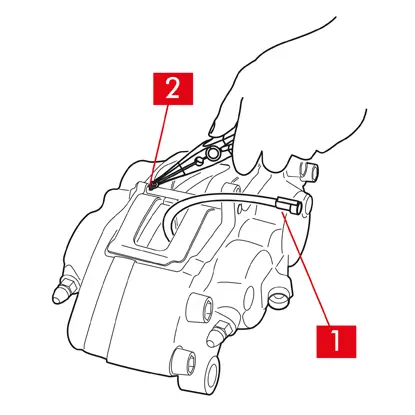
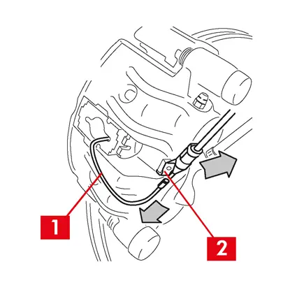
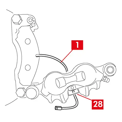
1. Odpojte kabel indikátoru opotřebení (bod 1), pokud je osazený, od koncovky ve vozidle: uvolněte jej ze příchytek na podvozku a třmenu.
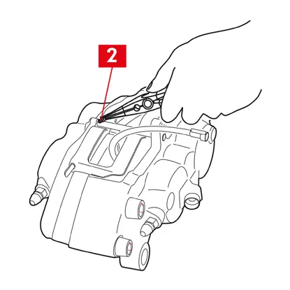
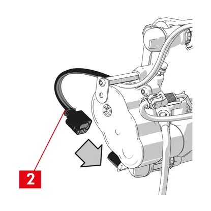
2. U modelů vybavených bezpečnostními závlačkami (bod 2) je odstraňte kleštěmi.
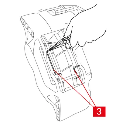
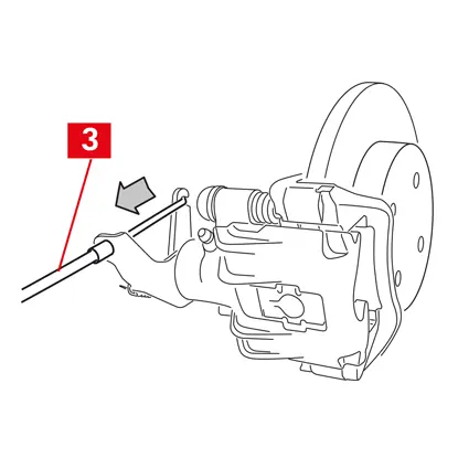
3. V případě dvoukotoučových třmenů vyndejte kleštěmi pružiny (bod 3).

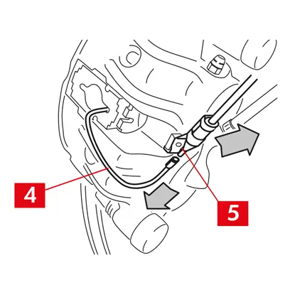
4. Vytáhněte čep/čepy (bod 4) kladivem a zarážečem. Vytáhněte je ručně ven a ujistěte se přitom, že držíte pružiny (bod 5) v dané poloze.
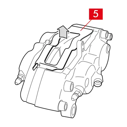
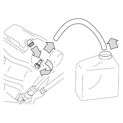
5. Vymontujte pružinu/pružiny (bod 5). Zkontrolujte hladinu kapaliny. Otevřete uzávěr nádrže brzdové kapaliny.
UPOZORNĚNÍ! Níže popsaným postupem pro odtlačení pístu se zvýší hladina brzdové kapaliny v nádržce. Ujistěte se, že hladina brzdové kapaliny nepřeteče, protože by se jí poškodily lakované partie vozidla.
PEVNÉ TŘMENY typu A B
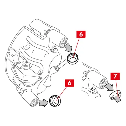
1. Lehce odtáhněte písty stahovákem nebo jiným vhodným nástrojem a zatlačením na destičky (bod 6).
Po odtlačení pístu dozadu se musí třmen nechat uvolnit z kotouče.
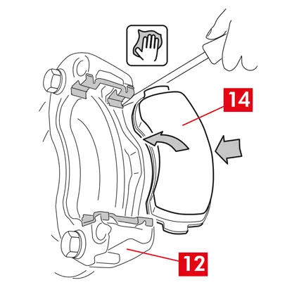
2. Pokud to konstrukce třmenu umožňuje, vymontujte destičky. Pokud ne, vyndejte je po rozebrání třmenu. Pokud chcete destičky znovu použít, vyznačte si nich fixem směr otáčení kotouče.
PLOVOUCÍ TŘMENY typu C
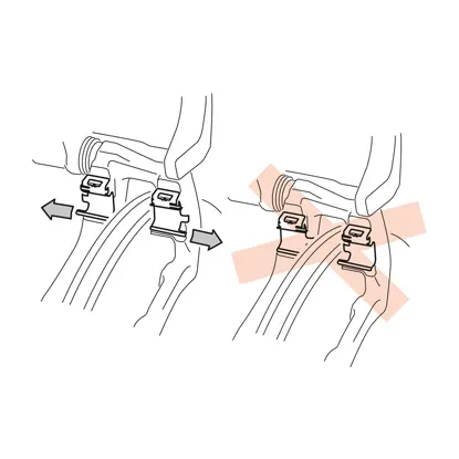
1. Vyjměte destičky a zároveň posuňte těleso třmenu dozadu a dopředu na vodicích pouzdrech (bod 7). Posunutím tělesa třmenu se destičky mírně oddálí od kotouče, což usnadňuje jejich vyjmutí.
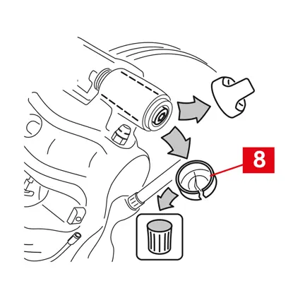
Pokud vrub způsobený opotřebením kotouče brání vytažení destiček, rozeberte těleso třmenu:
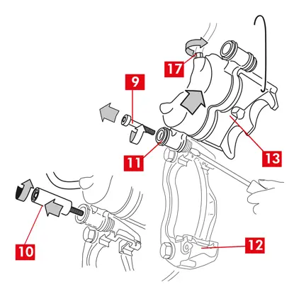
2. Vyšroubujte šrouby (bod 8) klíčem.
3. Šroubovákem vyjměte vodicí pouzdra ze sedel.
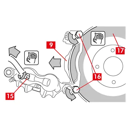
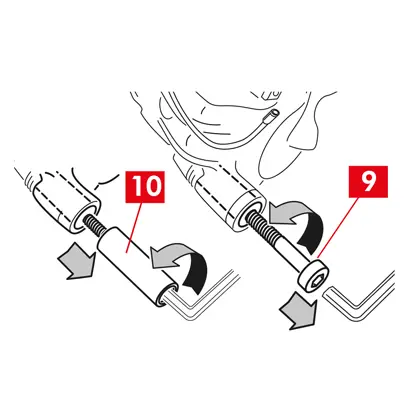
4. Vyjměte vodicí pouzdra (bod 7) natolik, aby se daly oddělit od držáku třmenu (bod 9).
5. Oddělte těleso třmenu (bod 10) od držáku třmenu (bod 9) a zavěste jej na podvozku vozidla pomocí háku ve tvaru S.
6. Vyndejte destičky.
7. Pokud chcete destičky znovu použít, vyznačte si nich fixem směr otáčení kotouče.
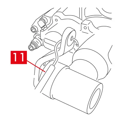
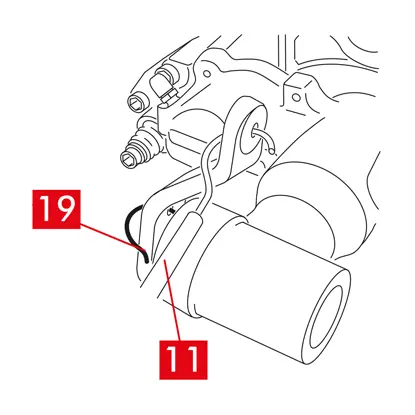
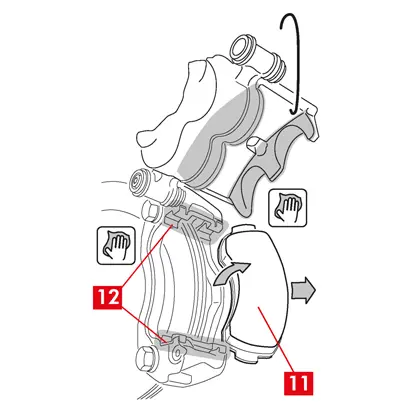
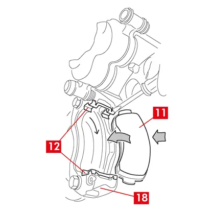
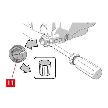
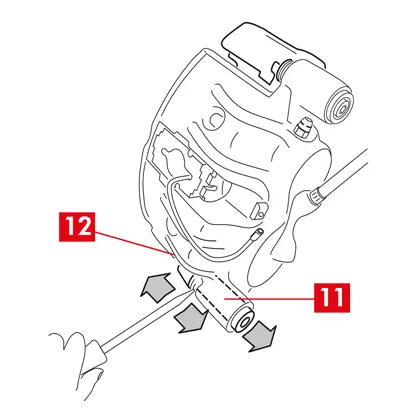
8. U zadních třmenů (s parkovacím mechanismem) odpojte bovden parkovací brzdy (bod 11).
NEBEZPEČÍ! Potrubí brzdové kapaliny musí zůstat volné, nesmí se napínat. Přílišným napnutím by potrubí mohlo prasknout a brzdová kapalina by mohla vytéct.
Všechny typy třmenů
1. Zavřete uzávěr nádrže brzdové kapaliny.
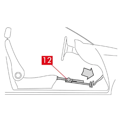
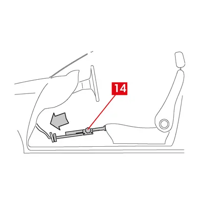
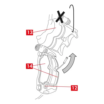
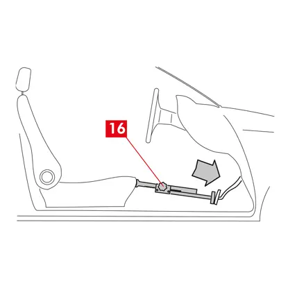
2. Do prostoru pro cestující umístěte mezi sedadlo a brzdový pedál umístěte rozpěrku (bod 12), abyste pedál zůstal stlačení po dobu provádění činností.
VAROVÁNÍ! Tím se uzavře hydraulický okruh brzd a zamezí únikům brzdové kapaliny.
UPOZORNĚNÍ! ěhem všech níže popsaných fází zajistěte, aby se brzdová kapalina nedostala na žádnou část vozidla, zejména na lakované díly: riziko poškození. Okamžitě otřete jakékoli náhodné potřísnění nebo úniky kapaliny kuchyňskou utěrkou a očistěte zasažené místo vodou.
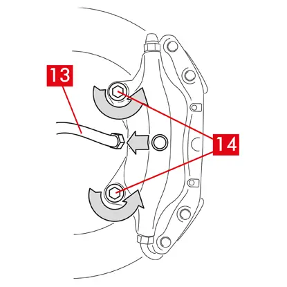
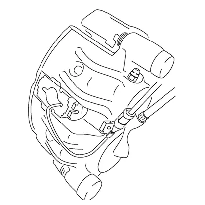
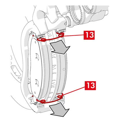
3. Povolte přívodní vedení (bod 13) na třmenu natolik, abyste se dalo odšroubovat rukou, zabráníte tak případnému úniku brzdové kapaliny.
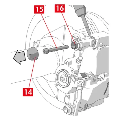
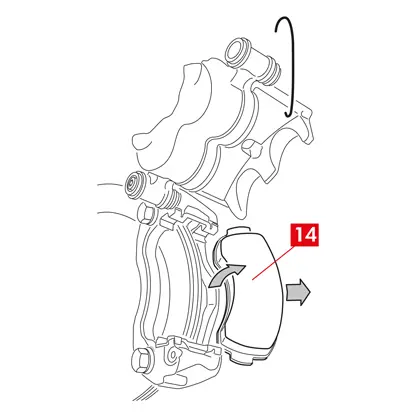
4. Odšroubujte otevřeným klíčem upevňovací šrouby (bod 14) a vyjměte třmen z nápravy.
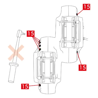
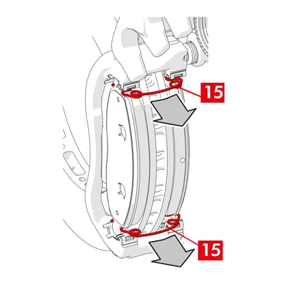
UPOZORNĚNÍ! U dvoukotoučových třmenů vyšroubujte pouze upevňovací šrouby nápravy. Nevyšroubujte spojovací šrouby (bod 15) polovin třmenu.
5. Odpojte přívodní vedení (bod 13) od třmenu.
6. Otřete bez prodlení případné úniky brzdové kapaliny.
7. Přívodní trubka musí být zvednutá, aby nemohla kapalina vytéct.
8. Vytáhněte třmen, který se má vyměnit.
8. Vytáhněte třmen, který se má vyměnit.
Postup při montáži
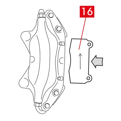
1. Zasuňte destičky (bod 16) do nového třmenu.
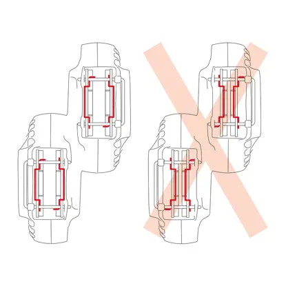
VAROVÁNÍ! Všechny šipky vyražené na destičkách musí ukazovat směr otáčení kotouče.
NEBEZPEČÍ! Destičky je nutné vložit tak, aby třecí materiál směřoval ke kotouči.
VAROVÁNÍ! Pokud to konstrukce třmenu umožňuje, lze podložky vložit i po namontování třmenu, rovnou po kroku „Utáhnout upevňovací šrouby“.
NEBEZPEČÍ! Ujistěte se, že třecí plochy nejsou znečištěné mazivem. Pokud ano, je nutné mastnotu odstranit brusným papírem.
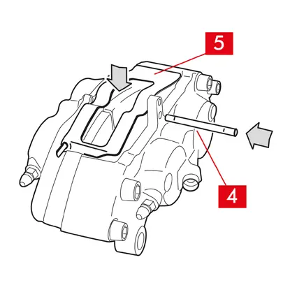
2. Znovu vložte pružiny (bod 5) a čepy (bod 4) do sedel ve třmenu a destičkách. Kolíky je nutné zarazit na doraz kladivem a zarážečem.
Při upevňování pružin dodržte správné směrování.
3. Zkontrolujte, zda jsou pružiny správně umístěné.
4. U modelů vybavených bezpečnostními závlačkami (bod 2) je upevněte zpět kleštěmi.
5. Zkontrolujte, zda jsou závlačky správně umístěné.
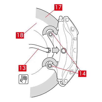
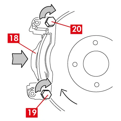
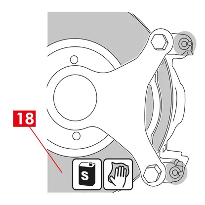
6. Očistěte brzdné plochy (bod 17) na kotouči (bod 18) odmašťovacím přípravkem (např. rozpouštědlem SE 47).
7. Umístěte nový třmen na nápravu a zasuňte kotouč (bod 18) mezi destičky.
8. Utáhněte otevřeným klíčem upevňovací šrouby (bod 14) utahovacím momentem doporučeným výrobcem vozidla.
Anebo použijte následující doporučené utahovací momenty:
| Typ šroubu | M12x1,25 | M12x1,5 | M14x1,5 |
| Utahovací moment | 115 Nm | 125 Nm | 180 Nm |
9. Připojte kabel indikátoru opotřebení, pokud je osazený, do koncovky ve vozidle a do všech příchytek na podvozku a třmenu.
10. Připojte zpět přívod brzdové kapaliny (bod 13).
11. Odstraňte rozpěrku, kterou jste předtím umístili do prostoru pro cestující, čímž se uvolní brzdový pedál a znovu otevře okruh.
12. U zadních třmenů typu C (s parkovacím mechanismem) připojte zpět bovden parkovací brzdy (bod 11).
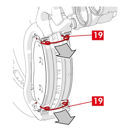
13. Odstraňte pojistný čep páky (bod 19).
14. Zatáhněte parkovací brzdu ve vozidle. Opakujte postup několikrát, dokud se zdvih páky brzdového mechanismu neustaví na minimálních hodnotách.
15. Otevřete uzávěr nádrže brzdové kapaliny.
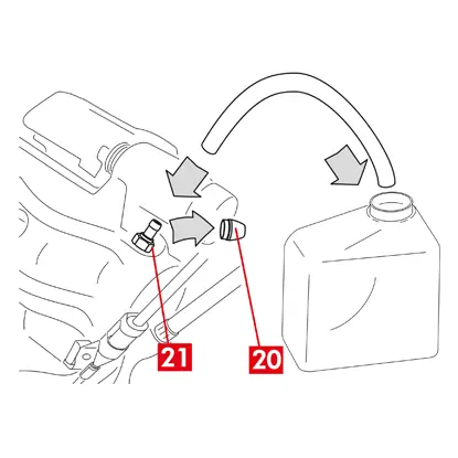
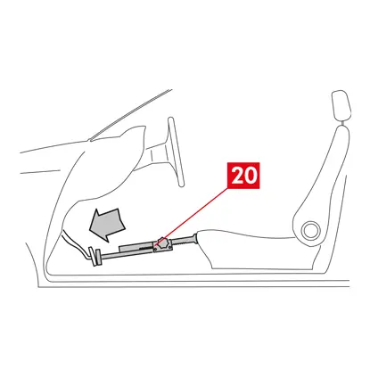
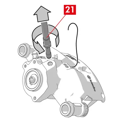
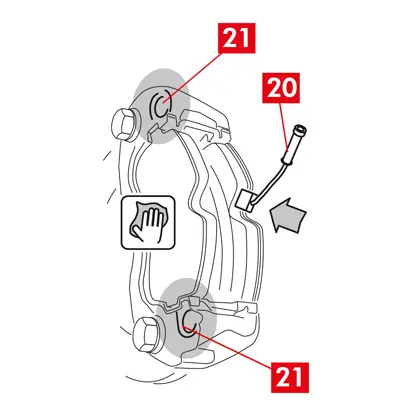
16. Odstraňte kryt (bod 20) a připojte k odvzdušňovací zátce (bod 21) na třmenu průhlednou trubku, kterou je nutné zaústit do nádržky tak, aby se dala vypustit veškerá kapalina.

17. Otevřete odvzdušňovací zátku (bod 21).
18. Sešlapujte brzdový pedál ve vozidle, dokud nezačne brzdová kapalina vytékat odvzdušňovací zátkou.
19. Držte pedál sešlápnutý a zavřete odvzdušňovací zátku. Uvolněte pedál, počkejte několik sekund, pak postup zopakujte opakujte, dokud nezačne vytékat kapalina bez vzduchových bublin a neobnoví se obvyklý odpor a dráha brzdového pedálu.
20. Utáhněte odvzdušňovací zátku utahovacím momentem uvedeným v tabulce:
| Odvzdušňovací zátka | M6x1 | M6x1 | M6x1 | M6x1 |
| Utahovací moment | 5÷7 Nm | 7÷10 Nm | 17÷20 Nm | 18÷22 Nm |
21. Oddělejte průhlednou trubku a umístěte krytku na odvzdušňovací zátku.
22. Proveďte odvzdušnění všemi dalšími odvzdušňovacími zátkami.
23. Po odvzdušnění odtlačte písty ve třmenu vhodným nástrojem (např. stlačovacím nářadím). Pak doplňte kapalinu podle doporučení výrobce.
24. Zavřete uzávěr nádrže brzdové kapaliny.
25. S motorem v chodu sešlápněte brzdový pedál vozidla na doraz a zkontrolujte, zda nedochází k úniku kapaliny třmenem nebo k nestandardnímu snížení tlaku v okruhu a také zda se rozsvítí zadní brzdová světla.
NEBEZPEČÍ! Pokud kapalina ze třmenu uniká, zopakujte všechny kroky uvedené v tomto dokumentu, abyste zjistili příčinu a problém odstranili.
26. U třmenů se zabudovanou parkovací brzdou připojte koncovku bovdenu parkovací brzdy k jejímu uložení ve třmenu. Opakovaně zabrzděte a odbrzděte parkovací brzdu v kabině.
27. Nasaďte kolo zpět!
28. Pokud jsou destičky nové, je nutné je zaběhnout: postupujte podle pokynů dodaných s náhradními destičkami.
Zde jsou uvedeny pokyny pro výměnu brzdových třmenů:
Plovoucí třmeny s prostřední pružinou
Plovoucí třmeny se dvěma nebo čtyřmi bočními pružinami a omezovacími pružinami zbytkového momentu.
Pokud není uvedeno jinak, informace uvedené v tomto návodu platí pro oba typy třmenů.
Postup při výměně
Před zahájením výměny se ujistěte, že náhradní díly použité k výměně jsou vhodné pro danou značku a model vozidla.
- Sundejte kolo.
- Pro zajištění správné zpětné montáže si poznamenejte polohu všech částečně nebo zcela vymontovaných dílů.
1. Odpojte indikátor opotřebení (bod 1), pokud je osazený, od svorky ve vozidle: uvolněte jej z podložky (bod 2), kterou jej upevněný ke třmenu, a od všech příchytek na podvozku.
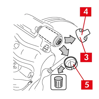
2. Odstraňte krytky (bod 3) z vodicích pouzder.
3. Pokud se jedná o krytku s okrajem (bod 4), odlomte ji zatažením za okraj (bod 4).
4. Pokud se jedná o krytku z tvrdého plastu (bod 5), odlomte ji šroubovákem. Tím krytka praskne.
VAROVÁNÍ! Demontovaná krytka z tvrdého plastu se nesmí použít znovu.
UPOZORNĚNÍ!! Vymontujte to vodicí pouzdro, které umožňuje otáčení tělesa třmenu bez protažení přívodního potrubí brzdové kapaliny.
VAROVÁNÍ! Existují dva typy vodicích krytek:
- se samostatným šroubem
- se zabudovaným šroubem
- se zabudovaným šroubem
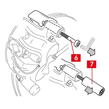
5. Pomocí klíče uvolněte a zcela vyjměte šroub (bod 6) nebo zabudované vodicí pouzdro (bod 7).
VAROVÁNÍ! Pokud se na třmen nalepily brzdové destičky, oddělte je šroubovákem.
NEBEZPEČÍ! Při otevření tělesa třmenu se může stát, že se uvolní omezovací pružiny zbytkového momentu.
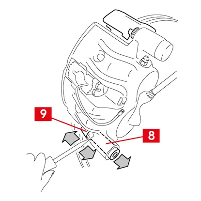
6. V případě nezabudovaného vodicího pouzdra (bod 8) vytáhněte toto pouzdro z držáku třmenu (bod 9) vypáčením šroubovákem ze sedla.
7. Při výměně třmenu na zadních kolech se zavěšením a listovými pružinami je nutné vymontovat obě vodicí pouzdra (bod 8), aby se těleso třmenu (bod 10) oddělilo od držáku třmenu (bod 9).
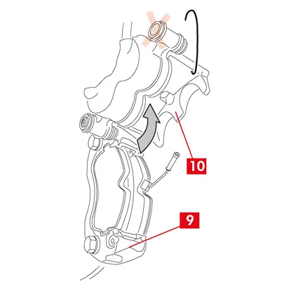
8. Těleso třmenu (bod 10) vytahujte z držáku třmenu (bod 9) otáčením okolo druhého vodicího pouzdra, dokud se destičky nedostanou z držáku třmenu. Těleso třmenu k podvozku vozidla upevněte vhodnými úchytkami.
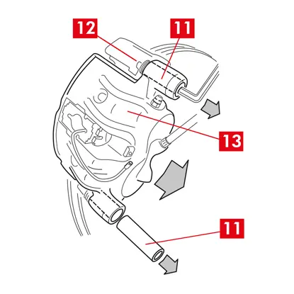
9. Vymontujte destičky (bod 11) a pružiny (bod 12) opatrně, aby se nepoškodily a daly se znovu namontovat na nový třmen.
10. Označte směr otáčení kotouče na destičkách, aby se daly správně namontovat zpět.
11. Vymontujte omezovací pružiny zbytkového moment (bod 13), pokud jsou stále na svém místě.
12. Do prostoru pro cestující umístěte mezi sedadlo a brzdový pedál umístěte rozpěrku (bod 14), abyste pedál zůstal stlačení po dobu provádění činností.
VAROVÁNÍ! Tím se uzavře hydraulický okruh brzd a zamezí únikům brzdové kapaliny.
UPOZORNĚNÍ! Během všech níže popsaných fází zajistěte, aby se brzdová kapalina nedostala na žádnou část vozidla, zejména na lakované díly: riziko poškození. Okamžitě otřete jakékoli náhodné potřísnění nebo úniky brzdové kapaliny kuchyňskou utěrkou a očistěte zasažené místo vodou.
13. Povolte přívodní vedení (bod 15) na třmenu natolik, abyste se dalo odšroubovat rukou, zabráníte tak případnému úniku brzdové kapaliny.
14. Odšroubujte otevřeným klíčem upevňovací šrouby (bod 16) a vyjměte držák třmenu (bod 9) z držáku náboje.
15. Odpojte přívodní vedení (bod 15) od tělesa třmenu.
16. Otřete bez prodlení případné úniky brzdové kapaliny.
17. Přívodní trubka musí být zvednutá, aby neunikala kapalina.
18. U třmenů se zabudovanou parkovací brzdou odpojte koncovku bovdenu parkovací brzdy od jejího uložení ve třmenu.
19. Vytáhněte třmen, který se má vyměnit.
20. Očistěte brzdné plochy (bod 17) na kotouči odmašťovacím přípravkem (např. Solvent SE47).
Postup pro upevnění třmenu
UPOZORNĚNÍ! Uzávěr plnicího otvoru kapaliny na novém třmenu neodstraňujte, dokud něho nepřipojíte přívodní vedení.
VAROVÁNÍ! EUH210 - Bezpečnostní list lze dodat na vyžádání.
VAROVÁNÍ! EUH208 - Obsahuje N-alkylovaný benzotriazol. Může způsobit alergické reakce.
1. Odstraňte ochranná víka z pouzder, pokud jsou osazená.
2. Uvolněte šrouby nebo vodicí pouzdra se zabudovaným šroubem.
3. V případě samostatných šroubů je zcela vyšroubujte.
4. Vytáhněte těleso třmenu z držáku třmenu.
VAROVÁNÍ! Pouzdra vytáhněte stranou víka, aby se nepoškodily prachovky.
5. Odstraňte kryty.
6. Všechny díly k namontování, sedla pouzder a uložení vík důkladně očistěte vhodnými prostředky (např. vlhkou utěrkou).
7. Očistěte montážní plochy na držáku náboje.
8. Umístěte nový držák třmene (bod 18) jeho vložením do kotouče.
9. Zasuňte a utáhněte dva upevňovací šrouby (body 19 a 20).
10. Utáhněte upevňovací šroub na straně vstupu do kotouče (bod 19) (s převodovým stupněm pro jízdu vpřed) utahovacím momentem doporučeným výrobcem vozidla.
11. Utáhněte druhý upevňovací šroub 20 (na straně výstupu z kotouče) utahovacím momentem doporučeným výrobcem vozidla.
Použijte následující doporučené utahovací momenty:
| Typ šroubu | Utahovací moment |
| M12x1,25 | 115 Nm |
| M12x1,5 | 125 Nm |
| M14x1,5 | 180 Nm |
| M16x1,5 | 210 Nm |
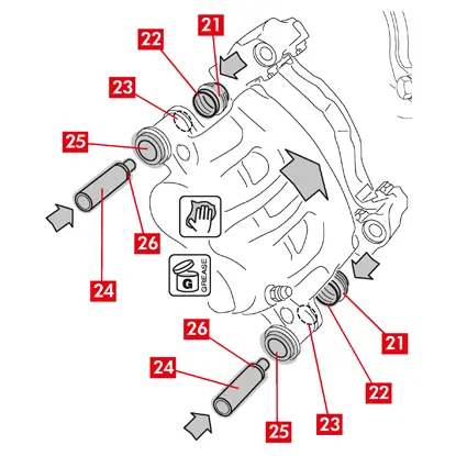
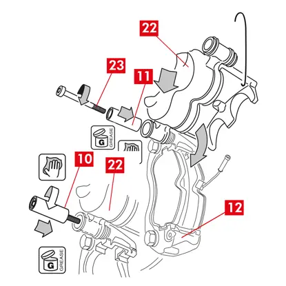
12. Namažte rovnoměrně celý vnitřní povrch krytů (bod 21) a styčný profil (bod 22) s tělesem třmenu.
13. Vložte kryty (bod 21) do uložení (bod 23) na tělese třmenu.
UPOZORNĚNÍ! Zkontrolujte prstem, zda byl kryt správně zasunutý a vložený do tělesa třmenu.
14. Namažte vnější povrch pouzder (bod 24) a jejich sedla (bod 25) v tělese třmenu, vložte pouzdra do tělesa třmenu ze strany naproti krytu.
15. Zatlačte na pouzdra (bod 24) tak, aby kryty (bod 21) zapadly do svého uložení (bod 26).
16. Odstraňte přebytečné mazivo.
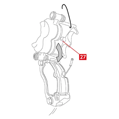
17. Nasaďte těleso třmenu na držák třmenu zasunutím a zašroubováním šroubu nebo zabudovaného pouzdra na výstupní straně kotouče (s převodovým stupněm pro jízdu vpřed).
18. Těleso třmenu (bod 27) vytahujte z držáku třmenu (bod 18) otáčením okolo vodicího pouzdra, dokud se destičky nedostanou do držáku třmenu. Těleso třmenu k podvozku vozidla upevněte vhodnými úchytkami.
UPOZORNĚNÍ! Nepoužívejte sedadla vodicích pouzder jako upevňovací místa.
Montáž destiček
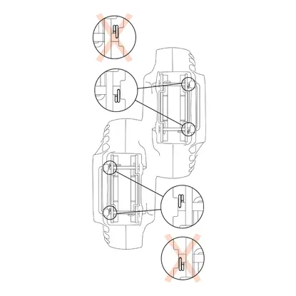
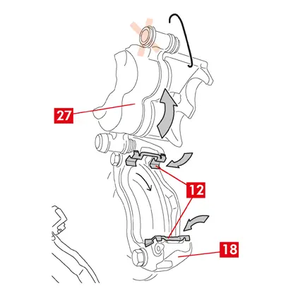
1. Tam, kde je to stanovené, namontujte boční pružiny (bod 12) do držáku třmenu a bezpečně je upevněte vhodným stlačením.
2. V případě třmenů se čtyřmi pružinami namontujte tyto pružiny tak, aby lamely směřovaly ven z držáku třmenu.
UPOZORNĚNÍ! Dodržte správný směr montáže.
VAROVÁNÍ! V případě destiček s lepicí stranou je nutné namontovány nové destičky podle pokynů dodaných s náhradními destičkami.
UPOZORNĚNÍ! Destičku s indikátorem opotřebení je nutné namontovat zpět do původní polohy.
UPOZORNĚNÍ! Dodržte správný směr montáže.
VAROVÁNÍ! V případě destiček s lepicí stranou je nutné namontovány nové destičky podle pokynů dodaných s náhradními destičkami.
UPOZORNĚNÍ! Destičku s indikátorem opotřebení je nutné namontovat zpět do původní polohy.
3. Vložte destičky (bod 11) zpět do držáku třmenu (bod 18). U třmenů typu B rozevřete šroubovákem boční pružiny (bod 12).
VAROVÁNÍ! Všechny šipky vyražené na destičkách musí ukazovat směr otáčení kotouče.
NEBEZPEČÍ! Destičky je nutné vložit tak, aby třecí materiál směřoval ke kotouči.
VAROVÁNÍ! Všechny šipky vyražené na destičkách musí ukazovat směr otáčení kotouče.
NEBEZPEČÍ! Destičky je nutné vložit tak, aby třecí materiál směřoval ke kotouči.
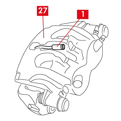
4. Protáhněte kabel indikátoru opotřebení (bod 1) příslušnou trasou takto:
U třmenů typu A - pružinou (bod 28).
U třmenů typu B - tělesem třmenu (bod 27).
4. Uzavřete opatrně třmen otočením tělesa třmenu (bod 27) okolo zašroubovaného vodicího pouzdra. Než dokončíte montáž těla třmenu, dejte pozor, aby u destiček s lepicí stranou nedošlo ke styku mezi tělesem třmenu a destičkou.
UPOZORNĚNÍ! Opatrně zavřete třmen a dbejte na to, aby se kryty na pouzdrech nepoškodily nárazem o držák třmenu.
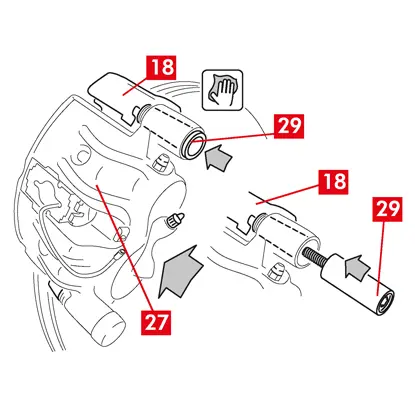
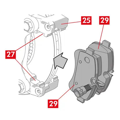
5. Přesuňte těleso třmenu (bod 27) směrem k držáku třmenu (bod 18).
6. Znovu zasuňte vodicí pouzdro (bod 29) do uložení držáku třmenu.
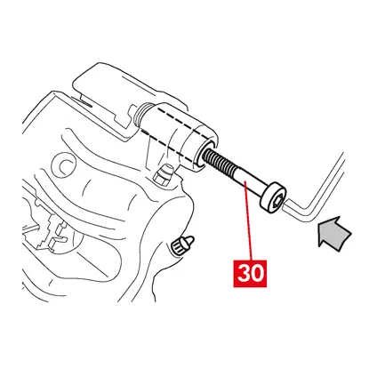
7. Vložte a zašroubujte nový šroub (bod 30), pokud je.
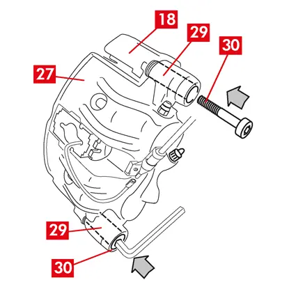
8. Při výměně třmenu na zadních kolech se zavěšením a listovými pery je třeba těleso třmenu (bod 27) znovu umístit na držák třmenu (bod 18), poté znovu nasunout obě vodicí pouzdra (bod 29) a vložit a utáhnout dva nové šrouby (bod 30), pokud jsou.
9. Pokud ještě není přišroubovaný upevňovací šroub vodicího pouzdra nebo zabudované vodicí pouzdro na vstupní straně do kotouče (při převodu vpřed), utáhněte je. Poté utáhněte na stejný moment druhý šroub nebo druhé zabudované vodicí pouzdro.
10. Utahujte utahovacím momentem uvedeným v následující tabulce:
| Typ | Utahovací moment | |
| Upevňovací šroub | (M8 – CH6) | 32 ÷ 36 Nm |
| Vodicí pouzdro se zabudovaným šroubem | (M8 – CH6) | 32 ÷ 36 Nm |
| Vodicí pouzdro se zabudovaným šroubem | (M10 – CH8) | 65 ÷ 75 Nm |
NEBEZPEČÍ! Dodržujte popsané pořadí utahování: nedodržení tohoto pořadí by se mohla ohrozit správné fungování třmenu.
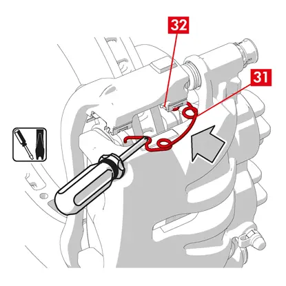
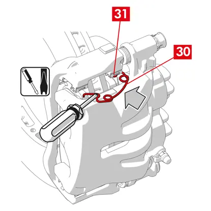
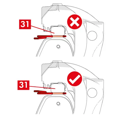
11. V případě omezovacích pružin zbytkového momentu (bod 31) zahákněte pružinu pod desku (bod 32) destičky a dutým šroubovákem zahákněte spodní stranu desky na druhé destičce.
NEBEZPEČÍ! Při nesprávném upevnění by se pružina mohla uvolnit.
UPOZORNĚNÍ! Dodržte správný směr montáže.
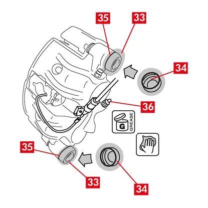
12. Díly (bod 33) očistěte pečlivě, aby byla jistota, že se budou držet v uložení. Nasaďte nové ochranné kryty (bod 34), namažte jejich vnitřní povrch a sedlo tělesa třmenu mazivem dodaným v sadě náhradních dílů.
13. Otočte ochranný kryt (bod 34) tak, aby zcela přilnul k sedlu (bod 35).
14. Připojte zpět indikátor opotřebení, pokud je osazený, ke koncovce ve vozidle. Zajistěte ho mírným přítlakem v podložce na třmenu a ve všech příchytkách na podvozku.
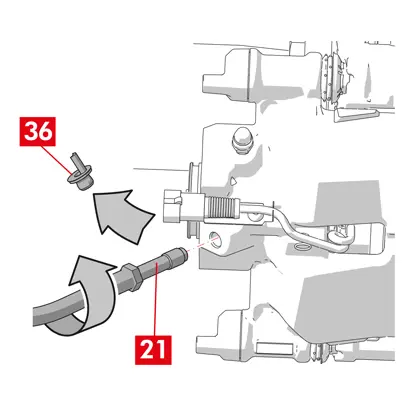
15. Odstraňte uzávěr plnicího otvoru brzdové kapaliny (bod 36).
16. Připojte zpět přívod brzdové kapaliny.
17. Odstraňte rozpěrku, kterou jste předtím umístili do prostoru pro cestující, čímž se uvolní brzdový pedál a znovu otevře hydraulický okruh.
18. Otevřete uzávěr nádrže brzdové kapaliny.
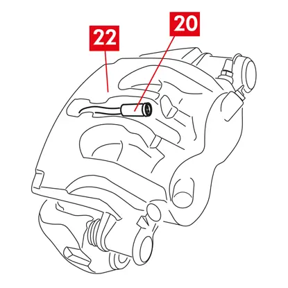
19. Odstraňte kryt (bod 37) a připojte k odvzdušňovací zátce (bod 38) na třmenu průhlednou trubku, kterou je nutné zaústit do nádržky tak, aby se dala vypustit veškerá kapalina.
20. Otevřete odvzdušňovací zátku (bod 38).
21. Sešlapujte brzdový pedál ve vozidle, dokud nezačne brzdová kapalina vytékat odvzdušňovací zátkou.
22. Držte pedál sešlápnutý a zavřete odvzdušňovací zátku. Uvolněte pedál, počkejte několik sekund, pak postup zopakujte opakujte, dokud nezačne vytékat kapalina bez vzduchových bublin a neobnoví se obvyklý odpor a dráha brzdového pedálu.
23. Utáhněte odvzdušňovací zátku utahovacím momentem uvedeným v tabulce:
| Odvzdušňovací zátka | M6x1 | M8x1,25 | M10x1 | M12x1 |
| Utahovací moment | 5÷7 Nm | 7÷10 Nm | 17÷20 Nm | 18÷22 Nm |
24. Oddělejte průhlednou trubku a umístěte krytku na odvzdušňovací zátku.
25. Proveďte odvzdušnění všemi dalšími odvzdušňovacími zátkami.
26. Po odvzdušnění odtlačte písty ve třmenu vhodným nástrojem (např. stlačovacím nářadím). Pak doplňte kapalinu podle doporučení výrobce.
27. Zavřete uzávěr nádrže brzdové kapaliny.
28. S motorem v chodu sešlápněte brzdový pedál vozidla na doraz a zkontrolujte, zda nedochází k úniku kapaliny třmenem nebo k nestandardnímu snížení tlaku v okruhu a také zda se rozsvítí zadní brzdová světla.
NEBEZPEČÍ! Pokud kapalina ze třmenu uniká, zopakujte všechny kroky uvedené v tomto dokumentu, abyste zjistili příčinu a problém odstranili.
29. U třmenů se zabudovanou parkovací brzdou připojte koncovku bovdenu parkovací brzdy k jejímu uložení ve třmenu.
30. Opakovaně zabrzděte a odbrzděte parkovací brzdu v kabině.
31. Nasaďte kolo zpět!
32. Pokud jsou destičky nové, je nutné je zaběhnout: postupujte podle pokynů dodaných s náhradními destičkami.
Zde jsou uvedené pokyny pro výměnu komponentů plovoucích třmenů užitkových vozidel (typ ECS53 a ECS60) s elektrickým parkovacím mechanismem:
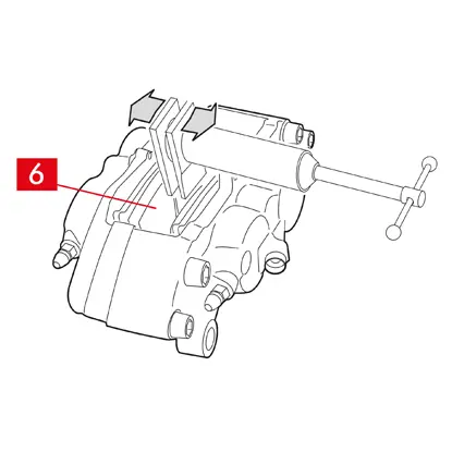
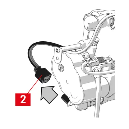
1. Akční člen
2. Destičky
3. Těleso třmenu (bez destiček a držáku třmenu)
4. Držák třmenu
2. Destičky
3. Těleso třmenu (bez destiček a držáku třmenu)
4. Držák třmenu
VAROVÁNÍ! Před výměnou náhradních dílů dodaných v balení si přečtěte tento dokument. Provádějte pouze ty kroky, které jsou nezbytné pro výměnu náhradního dílu nebo dílů dodaných v balení.
Postup při výměně
Před zahájením výměny se ujistěte, že náhradní díly použité k výměně jsou vhodné pro danou značku a model vozidla.
VAROVÁNÍ! V případě elektrické poruchy demontujte akční člen a zatlačte píst zpět, současně zašroubujte hvězdicovým klíčem šroub doprava.
- Pro zajištění správné zpětné montáže si poznamenejte polohu všech částečně nebo zcela vymontovaných dílů.
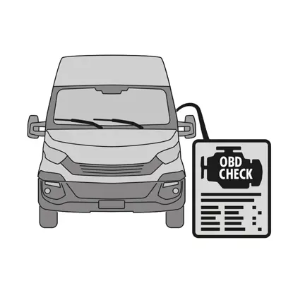
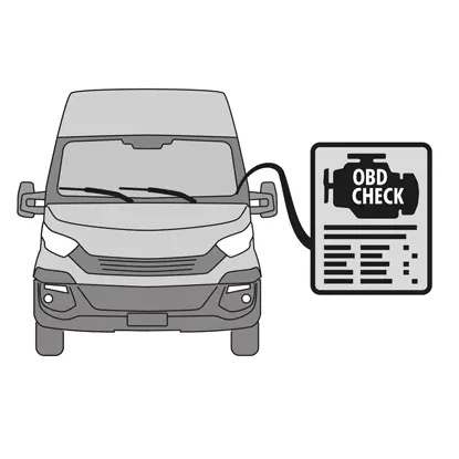
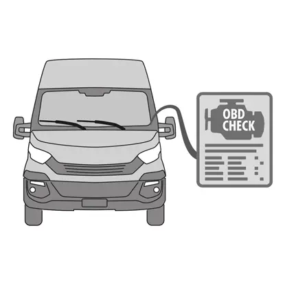
1. Připojte k vozidlu diagnostický přístroj (On Board Diagnosis - OBD) a přepněte ho na Maintenance Mode dle pokynů výrobce vozidla.
UPOZORNĚNÍ! Ujistěte se, že je náhradní díl kompatibilní se softwarem vozidla.
2. Sundejte kolo.
3. Uvolněte přívodní kabel akčního členu z kabelové průchodky.
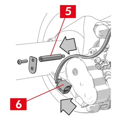
4. U třmenu typu ECS60 povolte a vyjměte kabelovou průchodku (bod 5).
5. Odpojte přívodní kabel (bod 6) od akčního členu.
VAROVÁNÍ! Konektor může být osazený pojistkou.
VAROVÁNÍ! Konektor může být osazený pojistkou.
Vymontování akčního členu
VAROVÁNÍ! Akční člen vymontujte pouze v případě, že je dostupný samostatný náhradní díl.
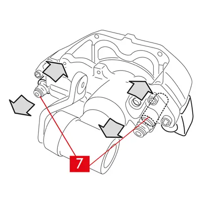
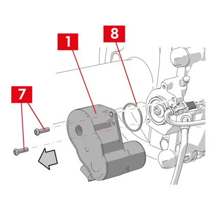
1. Uvolněte upevňovací šrouby (bod 7) z akčního členu (bod 1).
2. Vymontujte akční člen (bod 1).
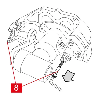
3. Vymontujte těsnění (bod 8).
Vymontování destiček
UPOZORNĚNÍ! Nepoškoďte díly, které se mají zamontovat zpět.
NEBEZPEČÍ! Zabraňte napnutí přívodního potrubí brzdové kapaliny.
NEBEZPEČÍ! Zabraňte napnutí přívodního potrubí brzdové kapaliny.
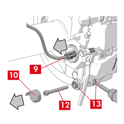
1. Odpojte indikátor opotřebení (bod 9), pokud je osazený, od svorky ve vozidle: uvolněte jej z podložky, kterou jej upevněný ke třmenu, a od všech příchytek na podvozku.
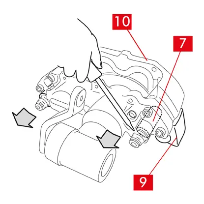
2. Odstraňte ochrannou krytku (bod 10) ze sekundárního pouzdra (strana výstupu kotouče pro otáčení dopředu).
3. Pokud se jedná o krytku z tvrdého plastu (bod 11), vypačte ji šroubovákem. Tím krytka praskne.
VAROVÁNÍ! Demontovaná krytka z tvrdého plastu se nesmí použít znovu.
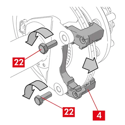
4. Povolte a vymontujte sekundární šroub (bod 12).
5. U třmenu typu ECS60 použijte šroubovák k vypáčení pouzdra z drážky, aby se dalo uvolnit z držáku třmenu.
6. Odstraňte ochrannou krytku (bod 14) z primárního pouzdra (strana vstupu kotouče pro otáčení dopředu).
7. Povolte primární šroub (bod 15) a vyjměte jej.
VAROVÁNÍ! Šroubovákem vypačte vodicí pouzdra z drážek.
8. Vyjměte primární vodicí pouzdro (bod 16) natolik, aby se dalo oddělit od držáku třmenu.
9. Vytáhněte těleso třmenu (bod 3) z držáku třmenu (bod 4), postupuje opatrně, aby se nenapnulo přívodní potrubí brzdové kapaliny.
10. Těleso třmenu k podvozku vozidla upevněte vhodnými úchytkami.
UPOZORNĚNÍ! Nepoužívejte sedadla pouzder jako upevňovací místa.
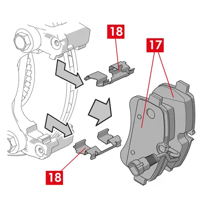
11. Vymontujte destičky (bod 17) a pružiny (bod 18) opatrně, aby se nepoškodily a daly se znovu namontovat na nový třmen.
12. Vymontujte omezovací pružiny zbytkového moment (bod 19), pokud jsou stále na svém místě.
VAROVÁNÍ! Pro správnou zpětnou montáž stejných destiček vyznačte na destičkách šipkami (pokud již nejsou vyznačené) směr otáčení kotouče.
Rozebrání tělesa třmenu
1. Do prostoru pro cestující umístěte mezi sedadlo a brzdový pedál umístěte rozpěrku (bod 20), abyste pedál zůstal stlačení po dobu provádění činností.
VAROVÁNÍ! Tím se uzavře hydraulický okruh brzd a zamezí únikům brzdové kapaliny.
UPOZORNĚNÍ! Během všech níže popsaných fází zajistěte, aby se brzdová kapalina nedostala na žádnou část vozidla, zejména na lakované díly: riziko poškození. Okamžitě otřete jakékoli náhodné potřísnění nebo úniky brzdové kapaliny kuchyňskou utěrkou a očistěte zasažené místo vodou.
2. Povolte přívodní vedení (bod 21) na třmenu natolik, abyste se dalo odšroubovat rukou, zabráníte tak případnému úniku brzdové kapaliny.
3. Odpojte přívodní vedení (bod 21) od tělesa třmenu.
4. Otřete bez prodlení případné úniky brzdové kapaliny.
5. Přívodní trubka musí být zvednutá, aby neunikala kapalina.
6. Vytáhněte těleso třmenu (bod 3).
Demontáž držáku třmenu
UPOZORNĚNÍ! Během demontáže držte držák třmenu na místě, aby nemohl vypadnout.
1. Uvolněte upevňovací šroub (bod 22).
2. Odstraňte držák třmenu (bod 4) z držáku náboje.
Postup při montáži

Namontujte náhradní díly.
1. Všechny díly k namontování (ať už nové či demontované díly), sedla pouzder a uložení pružin důkladně očistěte vhodnými prostředky (např. vlhkou utěrkou).
NEBEZPEČÍ! Zkontrolujte, zda nejsou díly poškozené. Případné poškozené díly vyměňte.
2. Očistěte montážní plochy (bod 23) na držáku náboje.
3. Očistěte brzdné plochy (bod 24) na kotouči odmašťovacím přípravkem (např. Solvent SE47).
Montáž držáku třmenu
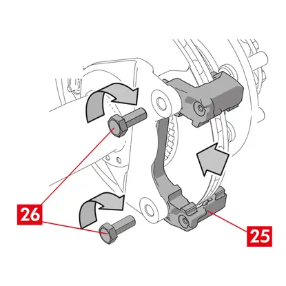
1. Umístěte nový držák třmenu (bod 25) do držáku náboje.
2. Vložte a utáhněte upevňovací šrouby (bod 26) utahovacím momentem doporučeným výrobcem vozidla.
Montáž destiček a tělesa třmenu
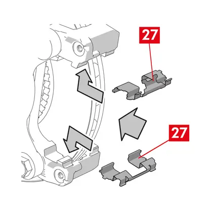
1. Vložte pružiny (bod 27) zpět správným směrem do uložení.
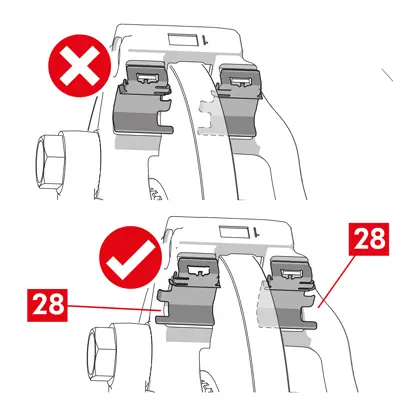
2. V případě třmenů ECS52 se čtyřmi pružinami namontujte tyto pružiny tak, aby lamely (bod 28) směřovaly ven z držáku třmenu.
VAROVÁNÍ! V případě destiček s lepicí stranou je nutné namontovány nové destičky podle pokynů dodaných s náhradními destičkami.
UPOZORNĚNÍ! Destičku s indikátorem opotřebení je nutné namontovat zpět do původní polohy.
NEBEZPEČÍ! Destičky je nutné vložit tak, aby třecí materiál směřoval ke kotouči.
3. Vložte destičky (bod 29) zpět do držáku třmenu (bod 25). Rozevřete šroubovákem boční pružiny (bod 27).
4. V případě omezovacích pružin zbytkového momentu (bod 30) zahákněte pružinu pod desku (bod 31) destičky a dutým šroubovákem zahákněte spodní stranu desky na druhé destičce.
NEBEZPEČÍ! Při nesprávném upevnění by se pružina mohla uvolnit.
NEBEZPEČÍ! Při nesprávném upevnění by se pružina mohla uvolnit.
UPOZORNĚNÍ! Dodržte správný směr montáže.
UPOZORNĚNÍ! Při montáži nového tělesa třmenu, neodstraňujte uzávěr plnicího otvoru kapaliny na novém třmenu, dokud k němu nepřipojíte přívodní vedení.
6. Umístěte těleso třmenu (bod 32) vložením do kotouče tak, aby se vodicí pouzdra kryla s otvory v držáku třmenu.
UPOZORNĚNÍ! Nepoškoďte víka.
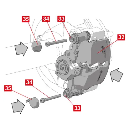
7. Zatlačte vodicí pouzdra (bod 33) do sedel v držáku třmenu.
8. Vložte a utáhněte šrouby (bod 34) utahovacím momentem 32 ÷ 36 Nm.
9. Umístěte krytky (bod 35).
UPOZORNĚNÍ! Před sejmutím ochranného uzávěru nechte přívodní bod co nejvýše a ujistěte se, že žádná brzdová kapalina uvnitř třmenu neuniká.
10. Připojte zpět kabel indikátoru opotřebení, pokud je osazený, ke koncovce ve vozidle. Zajistěte ho mírným přítlakem v podložce na třmenu, pokud je osazený, a ve všech příchytkách na podvozku.
Připojení přívodu brzdové kapaliny
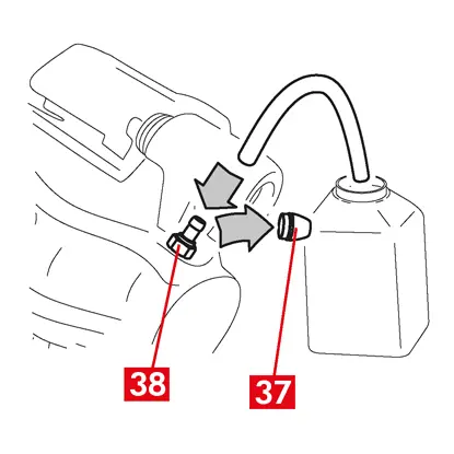
1. Odstraňte ochranný uzávěr (bod 36) plnicího otvoru brzdové kapaliny.
2. Připojte zpět přívod brzdové kapaliny (bod 21).
3. Odstraňte rozpěrku, kterou jste předtím umístili do prostoru pro cestující, čímž se uvolní brzdový pedál a znovu otevře okruh.
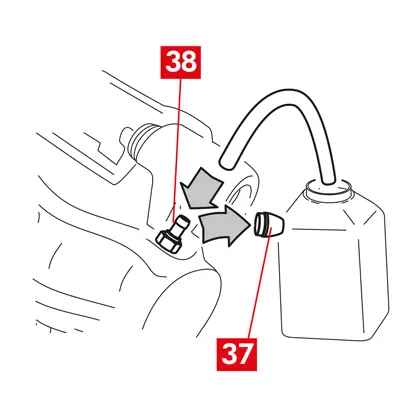
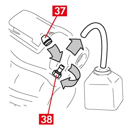
4. Odstraňte uzávěr (bod 37) odvzdušňovací zátky (bod 38).
5. Připojte k odvzdušňovací zátce (bod 38) na třmenu průhlednou trubku řádně zaústěnou nádržce, aby se dala vypustit veškerá kapalina.
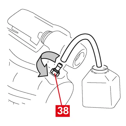
6. Otevřete odvzdušňovací zátku (bod 38).
7. Sešlapujte brzdový pedál ve vozidle, dokud nezačne brzdová kapalina vytékat odvzdušňovací zátkou.
8. Držte pedál sešlápnutý a zavřete odvzdušňovací zátku. Uvolněte pedál, počkejte několik sekund, pak postup zopakujte opakujte, dokud nezačne vytékat kapalina bez vzduchových bublin a neobnoví se obvyklý odpor a dráha brzdového pedálu.
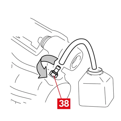
9. Utáhněte odvzdušňovací zátku (bod 38) utahovacím momentem uvedeným v následující tabulce:
| Typ odvzdušňovače | M10x1 |
| Utahovací moment | 12÷16 Nm |
10. Vyndejte průhlednou trubku.
11. Proveďte odvzdušnění všemi dalšími odvzdušňovacími zátkami.
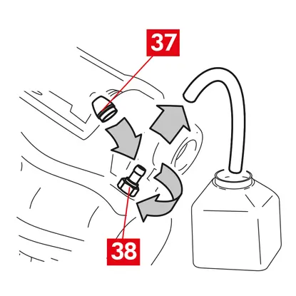
12. Umístěte zpět krytku (bod 37).
13. Po odvzdušnění odtlačte písty ve třmenu vhodným nástrojem (např. stlačovacím nářadím). Pak doplňte kapalinu podle doporučení výrobce.
14. S motorem v chodu sešlápněte brzdový pedál vozidla na doraz a zkontrolujte, zda nedochází k úniku kapaliny třmenem nebo k nestandardnímu snížení tlaku v okruhu a také zda se rozsvítí zadní brzdová světla.
NEBEZPEČÍ! Pokud kapalina ze třmenu uniká, zopakujte všechny kroky uvedené v tomto dokumentu, abyste zjistili příčinu a problém odstranili.
Montáž akčního členu
VAROVÁNÍ! Může se stát, že je akční člen již upevněný k tělesu třmenu.
Namontujte náhradní díly.
- Před zpětnou montáží případných demontovaných dílů je nutno tyto díly řádně očistit.
UPOZORNĚNÍ! Použijte jedině nové šrouby potřené lepidlem na závity. Použijte jedině nové těsnění.
NEBEZPEČÍ! Zkontrolujte, zda nejsou díly poškozené. Případné poškozené díly vyměňte.
1. Vyčistěte kontaktní plochu na třmenu a na akčním členu.
2. Ze sedel šroubů se závitem odstraňte zbytky lepidel na závitů.
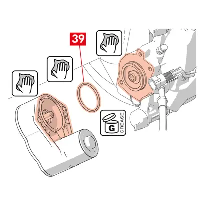
3. Těsnění (bod 39) očistěte a namažte dodaným mazivem.
4. Namažte vnitřní průměr spojky pohonné jednotky dodaným mazivem.
VAROVÁNÍ! EUH210 - Bezpečnostní list lze dodat na vyžádání.
VAROVÁNÍ! EUH208 - Obsahuje N-alkylovaný benzotriazol. Může způsobit alergické reakce.
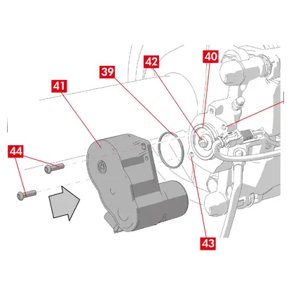
5. Umístěte těsnění (bod 39) do uložení (bod 40) v tělese třmenu.
6. Upevněte akční člen (bod 41) na šroub Torx (bod 42) na tělese třmenu.
7. Otočte akční člen (bod 41) tak, aby se otvory (bod 43) upevňovacích šroubů (bod 44) dostaly do jejich původní polohy.
UPOZORNĚNÍ! Při upevňování akčního členu na těleso třmenu se vyvarujte skřípnutí těsnění (bod 39).
8. Vložte a utáhněte upevňovací šrouby (bod 44) utahovacím momentem 7 ÷ 10 Nm.
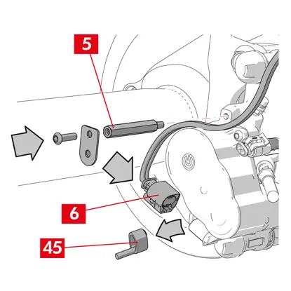
9. Odstraňte ochranný kryt (bod 45), pokud je osazený, a připojte elektrický přívodní kabel (bod 6).
10. Našroubujte kabelovou průchodku (bod 5), pokud byla demontovaná.
11. Upevněte přívodní kabel akčního členu (bod 6) v kabelové průchodce (bod 5).
Závěrečné fáze
1. Nasaďte kolo zpět!
2. Proveďte postup stanovený pro reset (Assembly check).
3. V případě potřeby resetujte počitadla (Reset Internal Counters) podle pokynů výrobce vozidla.
4. Odzkoušejte destičky, pokud je to stanoveno výrobcem vozidla.
5. Odpojte diagnostický přístroj. (On Board Diagnosis – OBD).
Zde jsou uvedeny pokyny pro výměnu tělesa třmenu pro plovoucí třmeny se dvěma nebo čtyřmi bočními pružinami a omezovacími pružinami zbytkového momentu.
Pokud se mají vyměnit pouze upevňovací šrouby, použijte jedině příslušné díly.
Postup při výměně
Před zahájením výměny se ujistěte, že náhradní díly použité k výměně jsou vhodné pro danou značku a model vozidla.
- Pro zajištění správné zpětné montáže si poznamenejte polohu všech částečně nebo zcela vymontovaných dílů.
- Sundejte kolo.
Třmeny ECS
VAROVÁNÍ! V případě elektrické poruchy demontujte akční člen (bod 5) a zatlačte píst zpět, současně zašroubujte hvězdicovým klíčem šroub doprava.

1. Připojte k vozidlu diagnostický přístroj (On Board Diagnosis - OBD) a přepněte ho na Maintenance Mode dle pokynů výrobce vozidla.
UPOZORNĚNÍ! Bez tohoto úkonu nelze píst zatlačit stahovákem nebo jiným vhodným nářadím.
UPOZORNĚNÍ! Ujistěte se, že je náhradní díl kompatibilní se softwarem vozidla.
2. Odpojte přívodní kabel (bod 2) od akčního členu.
VAROVÁNÍ! Konektor může být osazený pojistkou.
Všechny typy třmenů
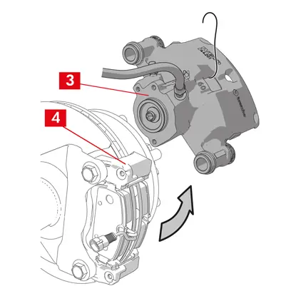
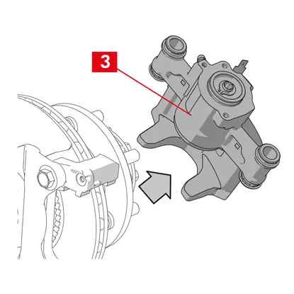
1. U třmenů s parkovací brzdou odpojte od třmenu ovládací táhlo (bod 3).
2. Odpojte indikátor opotřebení (bod 4), pokud je osazený, od svorky ve vozidle: uvolněte jej z podložky (bod 5), kterou jej upevněný ke třmenu, a od všech příchytek na podvozku.
3. Odstraňte krytky (bod 6) z vodicích pouzder.
4. Pokud se jedná o krytku s okrajem (bod 7), odlomte ji zatažením za okraj (bod 7).
5. Pokud se jedná o krytku z tvrdého plastu (bod 8), odlomte ji šroubovákem. Tím krytka praskne.
VAROVÁNÍ! Demontovaná krytka z tvrdého plastu se nesmí použít znovu.
UPOZORNĚNÍ! Vymontujte to vodicí pouzdro, které umožňuje otáčení tělesa třmenu bez protažení přívodního potrubí brzdové kapaliny.
VAROVÁNÍ! Jsou dva typy vodicích pouzder: se samostatným šroubem, se zabudovaným šroubem.
VAROVÁNÍ! Demontovaná krytka z tvrdého plastu se nesmí použít znovu.
UPOZORNĚNÍ! Vymontujte to vodicí pouzdro, které umožňuje otáčení tělesa třmenu bez protažení přívodního potrubí brzdové kapaliny.
VAROVÁNÍ! Jsou dva typy vodicích pouzder: se samostatným šroubem, se zabudovaným šroubem.
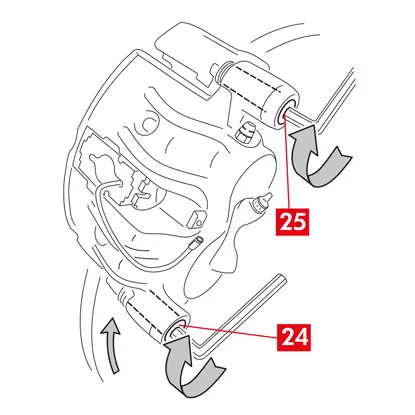
6. Vyšroubujte klíčem a vyjměte šroub (bod 9) nebo zabudované vodicí pouzdro (bod 10).
7. V případě nezabudovaného vodicího pouzdra (bod 11) vytáhněte toto pouzdro z držáku třmenu (bod 12) vypáčením šroubovákem ze sedla.
8. Při výměně třmenu na zadních kolech se zavěšením a listovými pružinami je nutné vymontovat obě vodicí pouzdra 11, aby se těleso třmenu (bod 13) zcela oddělilo od držáku třmenu (bod 12).
VAROVÁNÍ! Pokud se na třmen nalepily brzdové destičky, oddělte je pomocí šroubováku. Dávejte přitom pozor, aby se nepoškodily pryžové součásti třmenu.
NEBEZPEČÍ! Při otevření tělesa třmenu se může stát, že se uvolní omezovací pružiny zbytkového momentu.
9. Těleso třmenu (bod 13) vytahujte z držáku třmenu (bod 12) otáčením okolo druhého vodicího pouzdra, dokud se destičky (bod 14) nedostanou z držáku třmenu. Těleso třmenu k podvozku vozidla upevněte vhodnými úchytkami. Nepoužívejte sedadla pouzder jako upevňovací místa.
11. Vymontujte destičky (bod 14) tak, aby se nic nepoškodilo.
12. Označte směr otáčení kotouče na destičkách, aby se daly správně namontovat zpět.
14. Vymontujte omezovací pružiny zbytkového moment (bod 15), pokud jsou stále na svém místě.
15. Do prostoru pro cestující umístěte mezi sedadlo a brzdový pedál umístěte rozpěrku (bod 16), abyste pedál zůstal stlačení po dobu provádění činností.
VAROVÁNÍ! Tím se uzavře hydraulický okruh brzd a zamezí únikům brzdové kapaliny.
UPOZORNĚNÍ! Během všech níže popsaných fází zajistěte, aby se brzdová kapalina nedostala na žádnou část vozidla, zejména na lakované díly: riziko poškození. Okamžitě otřete jakékoli náhodné potřísnění nebo úniky brzdové kapaliny kuchyňskou utěrkou a očistěte zasažené místo vodou.
UPOZORNĚNÍ! Během všech níže popsaných fází zajistěte, aby se brzdová kapalina nedostala na žádnou část vozidla, zejména na lakované díly: riziko poškození. Okamžitě otřete jakékoli náhodné potřísnění nebo úniky brzdové kapaliny kuchyňskou utěrkou a očistěte zasažené místo vodou.
16. Povolte přívodní vedení (bod 17) na třmenu natolik, abyste se dalo odšroubovat rukou, zabráníte tak případnému úniku brzdové kapaliny.
17. Vyšroubujte klíčem a vyjměte šroub (bod 9) nebo zabudované vodicí pouzdro (bod 10).
18. V případě nezabudovaného vodicího pouzdra (bod 11) vytáhněte toto pouzdro z držáku třmenu (bod 12) vypáčením šroubovákem ze sedla.
19. Vytáhněte těleso třmenu (bod 13) z držáku třmenu (bod 12), postupuje opatrně, aby se nenapnulo přívodní potrubí brzdové kapaliny.
20. Odpojte přívodní vedení (bod 17) od tělesa třmenu.
21. Otřete bez prodlení případné úniky brzdové kapaliny.
22. Přívodní trubka musí být zvednutá, aby neunikala brzdová kapalina.
23. Vytáhněte třmen, který se má vyměnit.
24. U třmenů se zabudovanou parkovací brzdou odpojte koncovku bovdenu parkovací brzdy od jejího uložení ve třmenu.
25. Očistěte brzdné plochy na kotouči odmašťovacím přípravkem (např. Solvent SE47).
Montáž destiček
UPOZORNĚNÍ! V případě destiček s lepicí stranou je nutné namontovány nové destičky podle pokynů dodaných s náhradními destičkami.
1. Zkontrolujte, zda jsou pružiny správně umístěné. V případě třmenů se čtyřmi pružinami namontujte tyto pružiny tak, aby lamely směřovaly ven z držáku třmenu.
UPOZORNĚNÍ! Při nesprávném umístění pružin se může způsobit úraz.
2. Zasuňte destičky (bod 14) do držáku třmenu (bod 12). Zatlačte přitom šroubovákem na boční pružiny.
VAROVÁNÍ! Všechny šipky vyražené na destičkách musí ukazovat směr otáčení kotouče.
NEBEZPEČÍ! Destičky je nutné vložit tak, aby třecí materiál směřoval ke kotouči.
UPOZORNĚNÍ! Destičku s indikátorem opotřebení je nutné namontovat zpět do původní polohy.
VAROVÁNÍ! Všechny šipky vyražené na destičkách musí ukazovat směr otáčení kotouče.
NEBEZPEČÍ! Destičky je nutné vložit tak, aby třecí materiál směřoval ke kotouči.
UPOZORNĚNÍ! Destičku s indikátorem opotřebení je nutné namontovat zpět do původní polohy.
3. V případě přítomnosti indikátoru opotřebení (bod 20) připojte jeho koncovku k destičce proti pístům a v případě potřeby ji vyměňte.
UPOZORNĚNÍ! Při připojování koncovky indikátoru opotřebení se ujistěte, že nejvíce vyčnívající část směřuje ke třecí ploše destičky.
UPOZORNĚNÍ! Při připojování koncovky indikátoru opotřebení se ujistěte, že nejvíce vyčnívající část směřuje ke třecí ploše destičky.
Montáž tělesa třmenu
UPOZORNĚNÍ! U třmenů s parkovací brzdou: při demontáži tělesa třmenu z brzdového kotouče a/nebo pokud chybí brzdové destičky, nepohybujte pístem ani hydraulicky, ani pomocí páky, protože by se mohla poškodit pružina a/nebo by mohla začít unikat brzdová kapalina.
1. Na držáku třmenu očistěte vlhkou utěrkou oblasti (bod 21) pro sesazení s tělesem třmenu (sedla vedení).
UPOZORNĚNÍ! Nepoužívejte přípravky, které by mohly poškodit ochranné kryty, jako je například nitro-tetrachlorethylenové ředidlo, benzín atd.
2. Očistěte a rovnoměrně namažte celý vnitřní povrch krytů, vnější povrch vodicích pouzder a jejich sedel v tělese třmenu.
3. Umístěte nové těleso třmenu (bod 22) a jedno ze dvou vodicích pouzder (bod 10) vložte do sedla na držáku třmenu (bod 12).
UPOZORNĚNÍ! Neodstraňujte uzávěr plnicího otvoru brzdové kapaliny, dokud není trubka definitivně připojena.
UPOZORNĚNÍ! Neodstraňujte uzávěr plnicího otvoru brzdové kapaliny, dokud není trubka definitivně připojena.
4. V případě nezabudovaného vodicího pouzdra (bod 11), zasuňte a utáhněte nový šroub (bod 23).
5. Uzavřete opatrně třmen otočením tělesa třmenu (bod 22) okolo usazeného vodicího pouzdra.
UPOZORNĚNÍ! Opatrně zavřete třmen a dbejte na to, aby se kryty na pouzdrech nepoškodily nárazem o uložení třmenu. Vyměňte kryty, je-li třeba.
VAROVÁNÍ! Než dokončíte montáž těla třmenu, dejte pozor, aby u destiček s lepicí stranou nedošlo ke styku mezi tělesem a destičkou.
6. Protáhněte čidlo indikátoru opotřebení (point 20) příslušným otvorem v tělese třmenu (point 22).
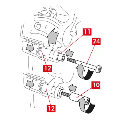
7. Zasuňte další vodicí pouzdro (bod 10) zpět do sedla držáku třmenu (bod 12).
8. V případě nezabudovaného vodicího pouzdra (bod 11), zasuňte a utáhněte nový šroub (bod 24).
UPOZORNĚNÍ! Při výměně držáku třmenu na zadních kolech se zavěšením a listovými pery je třeba těleso třmenu znovu umístit na držák třmenu, poté znovu nasunout obě vodicí pouzdra a vložit a utáhnout dva nové šrouby.
9. Utáhněte upevňovací šroub vodicího pouzdra nebo zabudované vodicí pouzdro (bod 24) na vstupní straně do kotouče (s převodovým stupněm pro jízdu vpřed). Pak utáhněte na stejný moment druhý šroub nebo zabudované vodicí pouzdro (bod 25).
10. Utahujte utahovacím momentem uvedeným v následující tabulce:
| Typ | Utahovací moment | |
| Upevňovací šroub | (M8 – CH6) | 32 ÷ 36 Nm |
| Vodicí pouzdro se zabudovaným šroubem | (M8 – CH6) | 32 ÷ 36 Nm |
| Vodicí pouzdro se zabudovaným šroubem | (M10 – CH8) | 65 ÷ 75 Nm |
NEBEZPEČÍ! Dodržujte popsané pořadí utahování: nedodržení tohoto pořadí by se mohla ohrozit správné fungování třmenu.
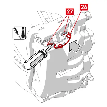
11. V případě omezovacích pružin zbytkového momentu (bod 26) zahákněte pružinu pod desku (bod 27) destičky a dutým šroubovákem zahákněte spodní stranu desky na druhé destičce.
NEBEZPEČÍ! Při nesprávném upevnění by se pružina mohla uvolnit.
UPOZORNĚNÍ! Dodržte správný směr montáže.
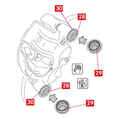
12. Díl (bod 28) očistěte pečlivě, aby byla jistota, že bude držet v uložení. Nasaďte nové ochranné kryty (bod 29), namažte jejich vnitřní povrch a sedlo tělesa třmenu mazivem dodaným v sadě náhradních dílů.
VAROVÁNÍ! EUH210 - Bezpečnostní list lze dodat na vyžádání.
VAROVÁNÍ! EUH208 - Obsahuje N-alkylovaný benzotriazol. Může způsobit alergické reakce.
VAROVÁNÍ! EUH208 - Obsahuje N-alkylovaný benzotriazol. Může způsobit alergické reakce.
13. Otočte ochranný kryty (bod 29) tak, aby zcela přilnuly k sedlu (bod 30).
14. Připojte zpět indikátor opotřebení, pokud je osazený, ke koncovce ve vozidle. Zajistěte ho mírným přítlakem v podložce na třmenu a ve všech příchytkách na podvozku.
15. Odstraňte uzávěr plnicího otvoru brzdové kapaliny.
16. Připojte zpět přívod brzdové kapaliny.
17. Odstraňte rozpěrku, kterou jste předtím umístili do prostoru pro cestující, čímž se uvolní brzdový pedál a znovu otevře okruh.
Třmeny s parkovací brzdou
UPOZORNĚNÍ! Před namontováním pístu s destičkami zkontrolujte, zda je připravený držák třmenu, destičky a kotouč.
- Píst s destičkami sestavte pomocí páky.
UPOZORNĚNÍ! Hydraulika se smí použít pouze v případě, kdy se píst nachází ve vzdálenosti méně než 1 mm od destiček.
Všechny typy třmenů
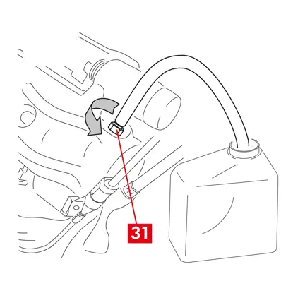
1. Připojte k odvzdušňovací zátce (bod 31) na třmenu průhlednou trubku řádně zaústěnou nádržce, aby se dala vypustit veškerá kapalina.
2. Otevřete odvzdušňovací zátku (bod 31).
3. Sešlapujte brzdový pedál ve vozidle, dokud nezačne brzdová kapalina vytékat odvzdušňovací zátkou.
4. Držte pedál sešlápnutý a zavřete odvzdušňovací zátku. Uvolněte pedál, počkejte několik sekund, pak postup zopakujte opakujte, dokud nezačne vytékat kapalina bez vzduchových bublin a neobnoví se obvyklý odpor a dráha brzdového pedálu.
5. Utáhněte odvzdušňovací zátku (bod 31) utahovacím momentem uvedeným v tabulce:
| Odvzdušňovací zátka | M6x1 | M8x1,25 | M10x1 | M12x1 |
| Utahovací moment | 5÷7 Nm | 7÷10 Nm | 17÷20 Nm | 18÷22 Nm |
6. Vyndejte průhlednou trubku.
7. Proveďte odvzdušnění všemi dalšími odvzdušňovacími zátkami.
8. Po odvzdušnění odtlačte písty ve třmenu vhodným nástrojem (např. stlačovacím nářadím). Pak doplňte kapalinu podle doporučení výrobce.
9. Zavřete uzávěr nádrže brzdové kapaliny.
10. S motorem v chodu sešlápněte brzdový pedál vozidla na doraz a zkontrolujte, zda nedochází k úniku kapaliny třmenem nebo k nestandardnímu snížení tlaku v okruhu a také zda se rozsvítí zadní brzdová světla.
NEBEZPEČÍ! Pokud kapalina ze třmenu uniká, zopakujte všechny kroky uvedené v tomto dokumentu, abyste zjistili příčinu a problém odstranili.
Třmeny s parkovací brzdou
- Připojte zpět indikátor opotřebení, pokud je osazený, ke koncovce ve vozidle. Zajistěte ho mírným přítlakem v podložce na třmenu a ve všech příchytkách na podvozku.
- Obnovte správné napnutí ovládacího táhla.
- Opakovaně zabrzděte a odbrzděte pákou parkovací brzdu v kabině vozidla, dokud se neobnoví obvyklý zdvih.
Třmeny ECS
1. Odstraňte ochranný kryt (pokud je osazený) a připojte elektrický přívodní kabel (bod 2).
2. Proveďte postup stanovený pro reset (Assembly check).
3. V případě potřeby resetujte počitadla (Reset Internal Counters) podle pokynů výrobce vozidla.
4. Odzkoušejte destičky, pokud je to stanoveno výrobcem vozidla.
5. Odpojte diagnostický přístroj (On Board Diagnosis - OBD).
Všechny typy třmenů
1. Nasaďte kolo zpět!
2. Pokud jsou destičky nové, je nutné je zaběhnout: postupujte podle pokynů dodaných s náhradními destičkami.
2. Pokud jsou destičky nové, je nutné je zaběhnout: postupujte podle pokynů dodaných s náhradními destičkami.
Omezení záruky
Tato záruka se vztahuje na všechny vady shodnosti, které se vyskytnou během dvou let od dodání zboží. Spotřebitel je povinen oznámit prodávajícímu vadu shodnosti do dvou měsíců ode dne zjištění uvedené vady, aniž je tím dotčena skutečnost, že promlčecí lhůta pro podání žaloby směřující k nápravě vady je dvacet šest měsíců od dodání zboží. V případě vady shodnosti má uživatel právo na opravu nebo výměnu zboží nebo na přiměřenou slevu z ceny nebo na ukončení smlouvy, jak stanoví čl. 130 spotřebitelského zákoníku, lze-li uplatnit.
Tato záruka představuje jedinou záruku poskytovanou v souvislosti s tímto výrobkem a nahrazuje všechny ostatní záruky, a to jak ústní, tak písemné.
Při zjištění vady je uživatel povinen:
- pod sankcí neplatnosti písemně oznámit vadu výrobci a prodejci do šedesáti dnů, současně dodat popis zjištěné závady výrobku nebo vrácených dílů a doklad o zakoupení výrobku včetně data nákupu (ať už se jedná o výrobek zakoupený v maloobchodě nebo prodaný prodejcem v rámci montáže tohoto výrobku);
- výrobek, u něhož je podezření na závadu, zaslat distribučním řetězcem do hlavního sídla firma Brembo S.p.A. na adresu Brembo 25 -24035 Curno (BG) - Italy.
Záruka nepokrývá:
- poškození výrobku způsobené částečně nebo zcela nesprávným použitím, dopravní nehodou, požárem, chemickou korozí, použitím k jiným než plánovaným účelům, nedovoleným použitím, použitím na jiném než zamýšleném modelu, nesprávnou montáží, montáží v rozporu s pokyny výrobce či nedostatečnou údržbu výrobku předepsanou výrobcem v dodaném návodu;
- reklamace ohledně jízdního komfortu, hlučnosti, vibrací nebo drsným jízdním vlastnostem.
Výrobek byl zkonstruovaný a vyrobený pro daný model a použití uvedeném v katalozích firmy Brembo a/nebo prodejců výrobků značky Brembo. Katalogy jsou dostupné na webových stránkách firmy Brembo (www.brembo.com). Výrobek se musí používat v souladu se zákony platnými ve státech a/nebo zemích používání vozidla, v němž je výrobek namontovaný, včetně a nejen dodržování předpisů dle Pravidel silničního provozu, a po získání všech autorizací/schválení, povolení nebo licencí předepsaných v daném státu a/nebo zemi.
Pro výrobky prodávané na území členských států Evropské unie platí tato záruční omezení v souladu s ustanoveními směrnice Rady 85/374/EHS ze dne 25. července 1985.
Pro výrobky prodávané na území Spojených států amerických platí tato záruční omezení v souladu s platnými federálními nebo státními zákony.
Všeobecné a bezpečnostní informace
Tyto výroby značky Brembo byly zkonstruované v souladu se všemi použitelnými bezpečnostními předpisy. Výrobky nejsou určené k jinému použití, než pro jaké byly vyvinuté a vyrobené. Použití k jakémukoli jinému účelu nebo jakákoli úprava či zásah do výrobku může ovlivnit výkon výrobku a může způsobit, že výrobek nebude bezpečný.
Taková úprava nebo nesprávné použití vede ke zrušení platnosti omezené záruky. V takovém případě může odpovědnost za zranění či poškození majetku třetích osob nést osoba, která výrobek používá.
Výstraha NEBEZPEČÍ! v těchto pokynech znamená postupy, jejichž nedodržení může s vysokou pravděpodobností způsobit vážný úraz nebo dokonce smrt. UPOZORNĚNÍ znamená postupy, jejichž nedodržení může způsobit fyzické poškození. VAROVÁNÍ! znamená postupy, jejichž nedodržení může způsobit poškození vozidla.
NEBEZPEČÍ!
Před zahájením výměny se ujistěte, že náhradní díly použité k výměně jsou vhodné pro danou značku a model vozidla. Tento výrobek je nezbytný pro bezpečný provoz vozidla, v němž je namontovaný. Je určený k namontování pouze znalou kvalifikovanou osobou, která byla vyškolena a/nebo má zkušenosti s montáží a použitím, pro něž je výrobek určen.
Montážní pracovník musí být vybaven patřičným nářadím a musí mít znalosti a zkušenosti ohledně opravování vozidla. Nesprávná nebo nesprávná montáž, ať už způsobená nedodržením tohoto návodu nebo jiným způsobem, má za následek zánik omezené záruky s tím, že v případě úrazu osob nebo poškození majetku se může odpovědnost přenést na montážního pracovníka.
Společnost Brembo neodpovídá za škody nebo úrazy způsobené osobě nebo osobou provozující vozidlo, do něhož byl náhradní díl zamontovaný.
UPOZORNĚNÍ!
S náhradními díly je nutné zacházet v souladu se zákony a předpisy.
Je nezbytné zamezit prudkým nárazům a/nebo poškození výrobku, jeho částí a součástí, protože to může snížit jejich účinnost a způsobit nesprávné fungování. Vyměňte případný poškozený díl nebo součást. Předcházení úrazům:
- Používejte patřičné osobní pracovní prostředky na ochranu před vdechnutím prachu uvolňovaného čistěním dílů.
- Při demontáži a zpětné montáži dílů s ostrými hranami používejte pracovní rukavice.
- Vyvarujte se přímého kontaktu pokožky s třecím materiálem na destičkách a brzdových čelistech: riziko odřenin.
- Při demontáži pístků třmenů pomocí stlačeného vzduchu nezasahujte rukama do uložení destiček: riziko rozdrcení rukou.
- Vyvarujte se přímého kontaktu s brzdovou kapalinou: riziko podráždění pokožky a očí. V případě náhodného zasažení je důkladně očistěte podle pokynů výrobce vozidla nebo brzdové kapaliny.
- Elektrické součástky nevystavujte elektrostatickému náboji ani nárazům, které by mohly poškodit plastové díly.
- Vymontované elektrické součástky chraňte před vlhkostí.
- Zajistěte správné zapojení všech elektrických kontaktů: zkontrolujte, zda se rozsvítí výstražné kontrolky. Pokud se výstražné kontrolky nerozsvítí, může to způsobit snížení účinnosti brzdového systému nebo nesprávné fungování brzdové signalizace.
- Zabraňte kontaktu tuků a jiných maziv s brzdnými plochami brzdového kotouče, bubnu, destiček a čelistí, protože by to mohlo ovlivnit účinnost brzdového systému a způsobit vážné fyzické poškození.
- Při montáži pryžových součástí nepoužívejte ostré nástroje, aby se tyto součásti nepoškodily. Ujistěte se, že byly vyměněné všechny poškozené díly.
Záruka
Zaručujeme, že tento výrobek splňuje specifikace výrobce a že neobsahuje vady materiálu a zpracování. Záruka má dobu trvání omezenou dva roky od data nákupu nebo delší dobu stanovenou zákonem. Záruka má dobu trvání omezenou dva roky od data nákupu nebo delší dobu stanovenou zákonem. Vadu je nutné nahlásit do 60 dnů od jejího zjištění a nejpozději do dvou let od data zakoupení. V případě, že se závada potvrdí a vztahuje se na ni záruka, bude výrobek opraven nebo vyměněn za nový či repasovaný. Záruka se nevztahuje na škody způsobené zcela nebo zčásti nesprávným použitím, požárem, chemickou korozí, nedovoleným použitím nebo použitím k jiným než zamýšleným účelům, použitím na jiném než určeném modelu, nesprávnou instalací nebo v rozporu s tím, co je stanoveno výrobcem či nedodržením plánem údržby výrobku dle předpisu výrobce v poskytnutých pokynech.
Je ještě něco, na co se chcete zeptat?
Kontaktujte tým technické podpory Brembo. Naši technici se vám ozvou co nejdříve!