


Pokyny na výmenu brzdových strmeňov na osobných a ľahkých úžitkových vozidlách
Prosím dodržujte všetky pokyny. Rovnaké pokyny nájdete na balení brzdových strmeňov. Nezabudnite ich uchovávať počas celej životnosti výrobku. V prípade predaja vozidla ich odovzdajte novému majiteľovi.
Tieto montážne pokyny sú návodom na štandardné opravy a nezohľadňujú žiadne zvláštnosti, ktoré sa môžu týkať rôznych brzdových systémov. Je potrebné podrobne dodržiavať špeciálne pokyny vydané výrobcami vozidiel a brzdových systémov.
Tieto montážne pokyny sú návodom na štandardné opravy a nezohľadňujú žiadne zvláštnosti, ktoré sa môžu týkať rôznych brzdových systémov. Je potrebné podrobne dodržiavať špeciálne pokyny vydané výrobcami vozidiel a brzdových systémov.
Tento dokument obsahuje pokyny na výmenu strmeňov:
1. Brzdové strmene s jedným kotúčom
2. Pevné strmene s dvoma kotúčmi
3. Plávajúce brzdové strmene s radiálne uloženými doštičkami, typ 2x60/68.
2. Pevné strmene s dvoma kotúčmi
3. Plávajúce brzdové strmene s radiálne uloženými doštičkami, typ 2x60/68.
Všetky informácie uvedené v tomto návode sa vzťahujú na všetky tri typy strmeňov, pokiaľ nie je uvedené inak.
Postup výmeny
Pred začatím výmeny sa uistite, že náhradné diely sú vhodné pre výmenu pre danú značku a model vozidla.
- Odstráňte koleso.
- Poznamenajte si polohu všetkých čiastočne alebo úplne demontovaných komponentov pre správnu spätnú montáž.
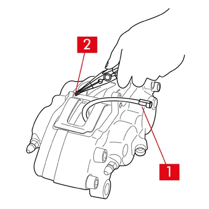
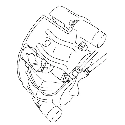
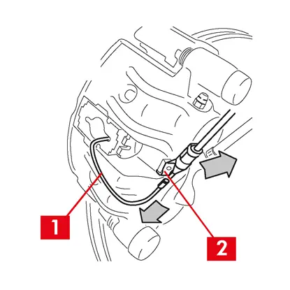
1. V prípade prítomnosti kábla indikátora opotrebenia (bod 1) ho odpojte od svorky vo vozidle a uvoľnite ho zo všetkých upevnení na podvozku a na strmeni.
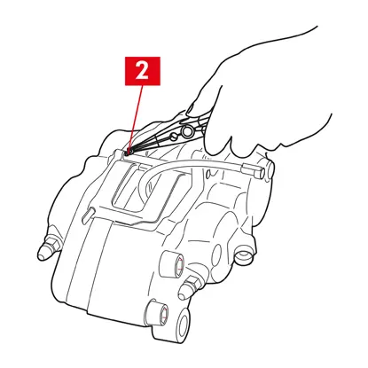
2. Pri modeloch vybavených bezpečnostnými závlačkami (bod 2) ich vytiahnite kliešťami.
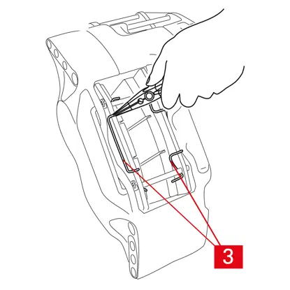
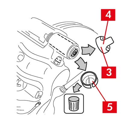
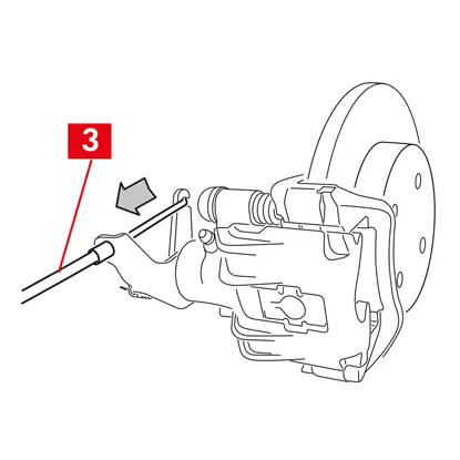
3. V prípade dvojkotúčových strmeňov vytiahnite pružiny (bod 3) kliešťami.
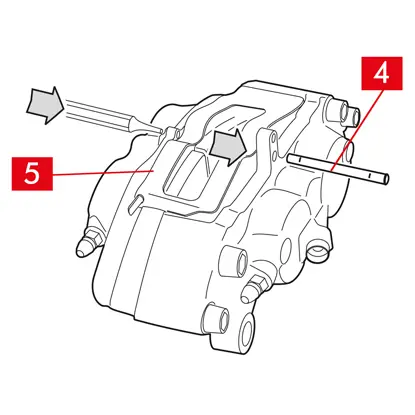
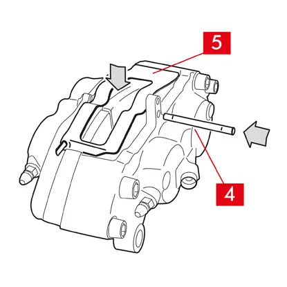
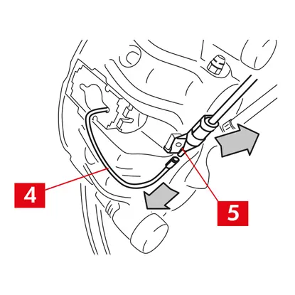
4. Vytiahnite kolík (-y) (bod 4) pomocou kladiva a nástroja na vytláčanie kolíka. Úplne ho vytiahnite rukou, pričom dbajte na to, aby pružiny (bod 5) zostali na svojom mieste.
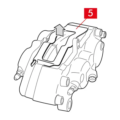
5. Odstráňte pružinu (-y) (bod 5). Skontrolujte hladinu kvapaliny. Otvorte uzáver nádržky brzdovej kvapaliny.
UPOZORNENIE! Nižšie opísané kroky na stiahnutie piestu spôsobia zvýšenie hladiny brzdovej kvapaliny v nádržke. Uistite sa, že hladina brzdovej kvapaliny neunikne, pretože by došlo k poškodeniu lakovaných častí vozidla.
PEVNÉ STRMENE typ A B
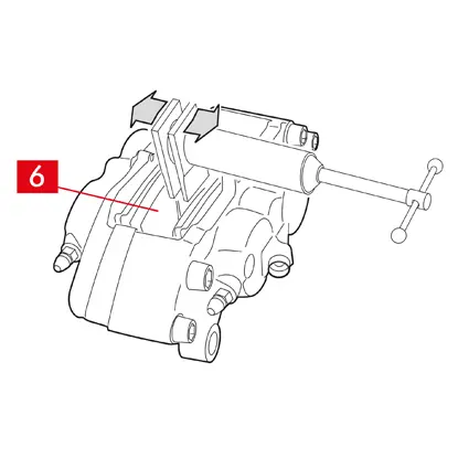
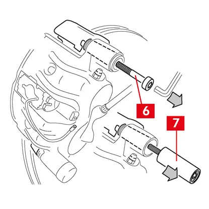
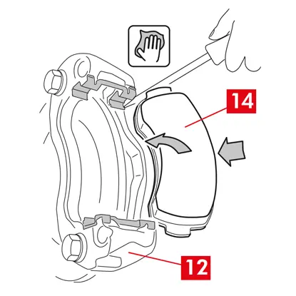
1. Piesty mierne odtiahnite pomocou sťahováka alebo iného vhodného nástroja a zatlačte na doštičky (bod 6).
Odtiahnutie piestu musí následne umožniť uvoľnenie strmeňa z kotúča.
2. Ak to konštrukcia strmeňa umožňuje, vyberte doštičky. V opačnom prípade ich odstráňte po demontáži strmeňa. Ak máte v úmysle opätovne použiť doštičky, označte na nich fixkou smer otáčania kotúča.
PLÁVAJÚCE STRMENE, typ C
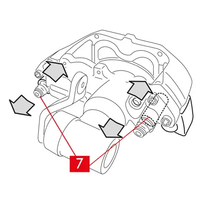
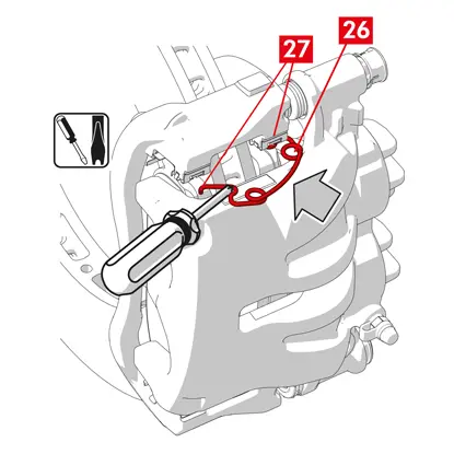
1. Vyberte doštičky a zároveň posuňte teleso strmeňa dozadu a dopredu na vodiacich puzdrách (bod 7). Posunutím telesa strmeňa sa doštičky mierne odtiahnu od kotúča, čím sa uľahčí ich vybratie.
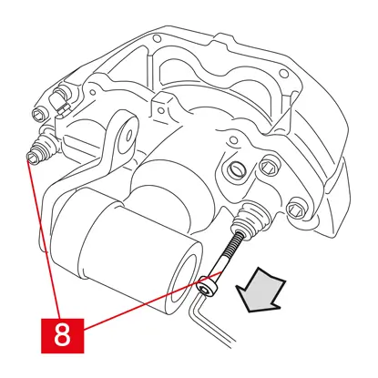
Ak preliačina vytvorená opotrebovaním kotúča bráni vybratiu doštičiek, demontujte teleso strmeňa:
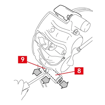
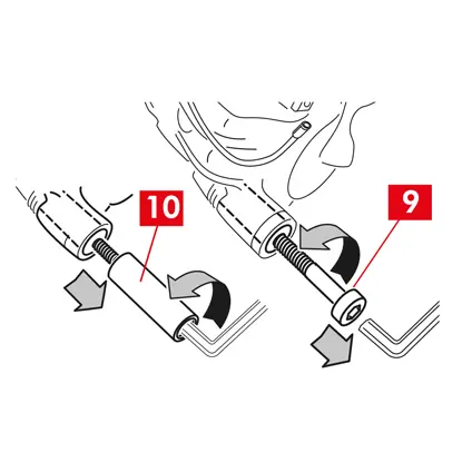
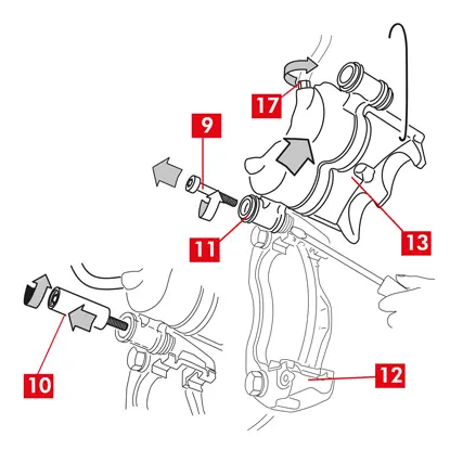
1. Demontujte skrutky (bod 8) pomocou kľúča
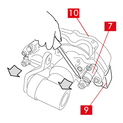
2. Pomocou skrutkovača vypáčte vodiace puzdrá z vyhradených sediel.
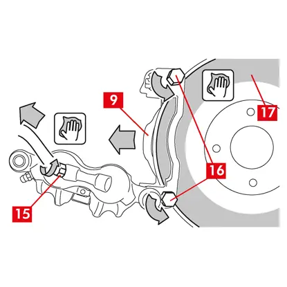
3. Vyberte vodiace puzdrá (bod 7) natoľko, aby ste ich mohli oddeliť od držiaka strmeňa (bod 9).
4. Úplne oddeľte teleso strmeňa (bod 10) od držiaka strmeňa (bod 9) a zaveste ho do podvozku vozidla pomocou háku v tvare písmena S.
5. Vyberte doštičky.
6. Ak máte v úmysle opätovne použiť doštičky, označte na nich fixkou smer otáčania kotúča.
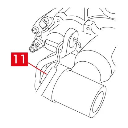
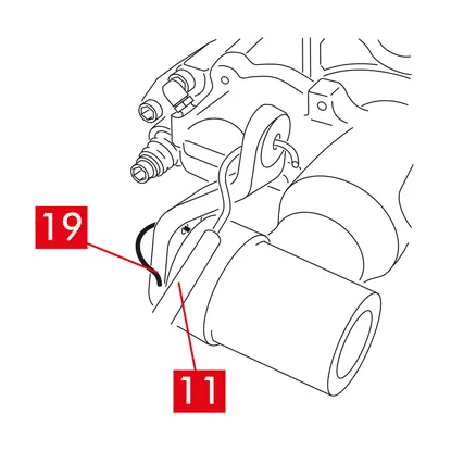
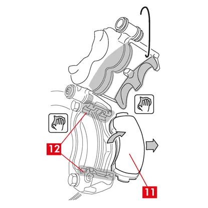
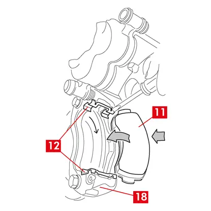
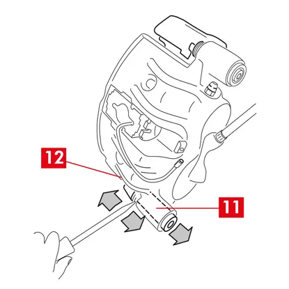
7. V prípade zadných brzdových strmeňov (s parkovacím mechanizmom) odpojte lanko ovládania parkovania (bod 11).
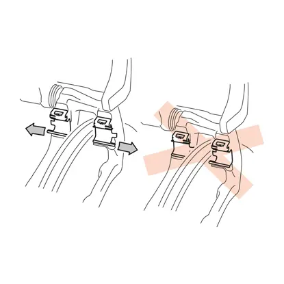
NEBEZPEČENSTVO! Vedenie brzdovej kvapaliny musí zostať voľné a nesmie byť natiahnuté. Ak by ste ich natiahli, mohli by sa pretrhnúť a brzdová kvapalina by mohla vytiecť.
Na všetky druhy strmeňov

1. Zatvorte uzáver nádržky brzdovej kvapaliny.
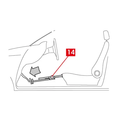
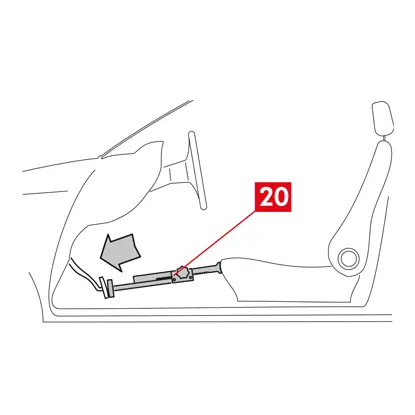
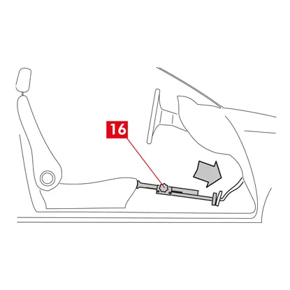
2. Umiestnite rozperu (bod 12) do priestoru pre cestujúcich medzi sedadlo a brzdový pedál, aby pedál zostal počas tejto práce stlačený.
VAROVANIE! Vďaka tomu je brzdový hydraulický okruh uzavretý, čím sa zabráni úniku brzdovej kvapaliny.
UPOZORNENIE! Počas všetkých ďalej opísaných fáz dbajte na to, aby sa brzdová kvapalina nedostala do kontaktu s časťami vozidla, ktoré by sa mohli poškodiť, najmä s lakovanými časťami. Prípadné náhodné postriekanie alebo únik kvapaliny okamžite utrite kuchynskou utierkou a očistite vodou.
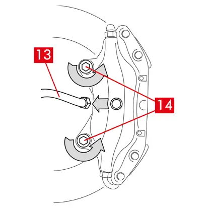
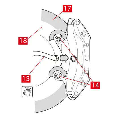
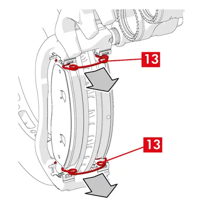
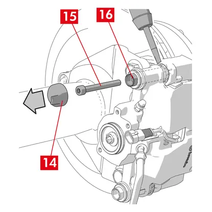
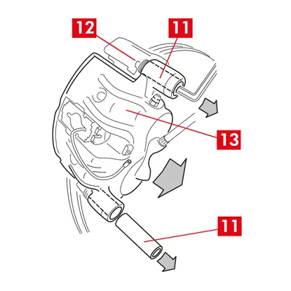
3. Uvoľnite prívodné potrubie (bod 13) na strmeni natoľko, aby ste ho mohli úplne odskrutkovať rukou, ale zabráňte úniku brzdovej kvapaliny.
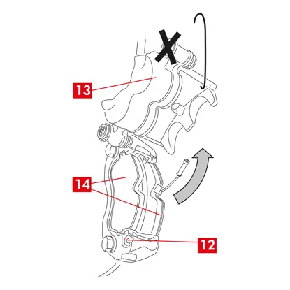
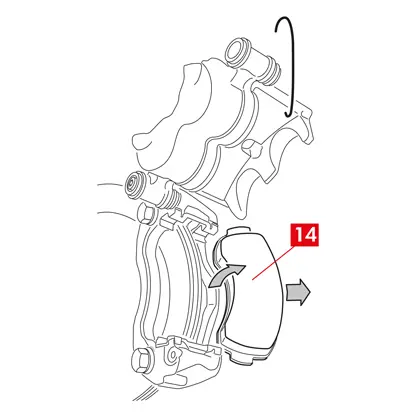
4. Vidlicovým kľúčom odskrutkujte upevňovacie skrutky (bod 14) a vyberte strmeň z nápravy.
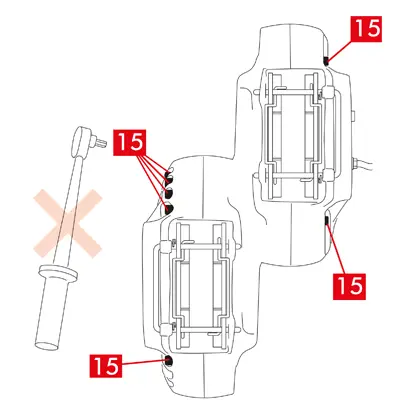
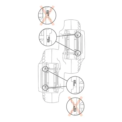
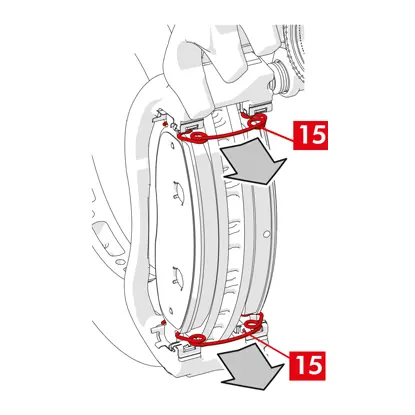
5. UPOZORNENIE! V prípade dvojkotúčových strmeňov demontujte iba upevňovacie skrutky nápravy. Nedemontujte skrutky (bod 15), ktoré spájajú polovičné strmene.
6. Úplne odpojte prívodné vedenie (bod 13) od strmeňa.
7. Okamžite zotrite prípadný únik brzdovej kvapaliny.
8. Držte prívodné vedenie v zdvihnutej polohe, aby ste zabránili náhodnému úniku kvapaliny.
9. Vytiahnite strmeň, ktorý sa má vymeniť.
9. Vytiahnite strmeň, ktorý sa má vymeniť.
Postup montáže
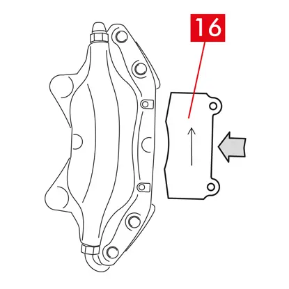
1. Vložte doštičky (bod 16) do nového strmeňa.
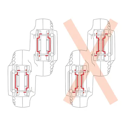
VAROVANIE! Všetky šípky vyrazené na doštičkách musia ukazovať v smere otáčania kotúča.
NEBEZPEČENSTVO! Doštičky musia byť vložené tak, aby bol trecí materiál otočený ku kotúču.
2. VAROVANIE!! Ak to konštrukcia strmeňa umožňuje, doštičky možno vložiť aj po nasadení strmeňa, a to hneď po „utiahnutí upevňovacích skrutiek“.
NEBEZPEČENSTVO! Skontrolujte, či trecie plochy nie sú znečistené mazivom, pretože inak budete musieť odstrániť všetky stopy maziva brúsnym papierom.
3. Pružiny (bod 5) a čapy (bod 4) vložte naspäť do vyhradených miest v strmeni a doštičkách. Kolíky sa musia zatĺcť až na doraz pomocou kladiva a nástroja na vytláčanie kolíka.
Pri montáži pružín dodržujte smer orientácie.
4. Skontrolujte, či sú pružiny v správnej polohe.
5. Pri modeloch vybavených bezpečnostnými závlačkami (bod 2) ich vložte naspäť kliešťami.
6. Skontrolujte, či sú závlačky v správnej polohe.
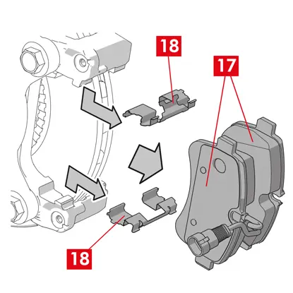
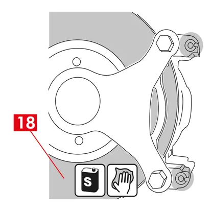
7. Očistite brzdovú plochu (bod 17) na kotúči (bod 18) pomocou odmasťovacieho prípravku (napr. rozpúšťadlo SE 47).
8. Nasaďte nový strmeň na nápravu a vložte kotúč (bod 18) medzi doštičky.
9. Upevňovacie skrutky (bod 14) utiahnite vidlicovým kľúčom s uťahovacím momentom odporúčaným výrobcom vozidla.
Prípadne použite nasledujúce odporúčané uťahovacie momenty:
| Typ skrutky | M12x1,25 | M12x1,5 | M14x1,5 |
| Uťahovací moment | 115 Nm | 125 Nm | 180 Nm |
10. V prípade prítomnosti kábla indikátora opotrebenia ho pripojte naspäť k svorke vo vozidle a k všetkým upevneniam na podvozku a na strmeni.
11. Pripojte naspäť prívodné vedenie brzdovej kvapaliny (bod 13).
12. Vyberte rozperu, ktorú ste predtým vložili do priestoru pre cestujúcich, čím uvoľníte pedál z brzdy a opätovne otvoríte okruh.
13. V prípade zadných brzdových strmeňov typu C (s parkovacím mechanizmom) pripojte naspäť lanko ovládania parkovania (bod 11).
14. Demontujte poistný kolík páčky (bod 19).
15. Zatiahnite parkovaciu brzdu vo vnútri vozidla. Postup opakujte niekoľkokrát, kým sa zdvih páčky brzdového mechanizmu nevráti na minimálne hodnoty.
16. Otvorte uzáver nádržky brzdovej kvapaliny.

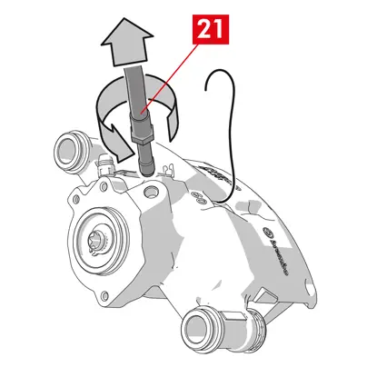
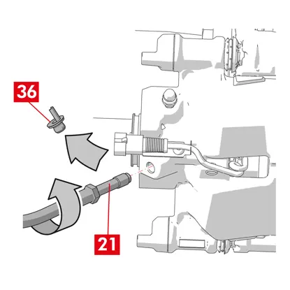
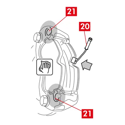
17. Demontujte ochranný uzáver (bod 20) a na odvzdušňovaciu zátku (bod 21) na strmeni pripojte priehľadnú hadičku, ktorej koniec vložte do nádoby na zachytávanie prípadnej kvapaliny.
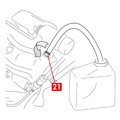
18. Otvorte odvzdušňovaciu zátku (bod 21).
19. Opakovane stláčajte brzdový pedál vozidla, kým z odvzdušňovacej zátky nezačne vytekať brzdová kvapalina.
20. Podržaním pedálu zatvorte odvzdušňovaciu zátku. Uvoľnite pedál, počkajte niekoľko sekúnd, potom postup opakujte, kým nebude vytekať kvapalina bez vzduchových bublín a kým sa neobnoví obvyklý odpor a zdvih brzdového pedála.
21. Odvzdušňovaciu zátku utiahnite uťahovacím momentom uvedeným v tabuľke:
| Odvzdušňovacia zátka | M6x1 | M6x1 | M6x1 | M6x1 |
| Uťahovací moment | 5÷7 Nm | 7÷10 Nm | 17÷20 Nm | 18÷22 Nm |
22. Demontujte priehľadnú hadičku a nasaďte ochranný uzáver na odvzdušňovaciu zátku.
23. Zopakujte postup odvzdušňovania na všetkých ostatných odvzdušňovacích zátkach.
24. Po odvzdušnení úplne stiahnite piesty v strmeni pomocou vhodného nástroja (napr. sťahováka) a potom doplňte hladinu kvapaliny podľa odporúčania výrobcu.
25. Zatvorte uzáver nádržky brzdovej kvapaliny.
26. Pri naštartovanom motore silno stlačte brzdový pedál vozidla a skontrolujte, či nedochádza k úniku kvapaliny zo strmeňa alebo k abnormálnym poklesom tlaku v okruhu a či sa rozsvietia zadné brzdové svetlá.
NEBEZPEČENSTVO! Ak kvapalina uniká zo strmeňa, zopakujte všetky kroky uvedené v tomto dokumente, aby ste určili príčinu a odstránili problém.

27. V prípade strmeňov so zabudovanou parkovacou brzdou pripojte koncovku kábla parkovacej brzdy k jej sedlu na strmeni. Opakovane zatiahnite a uvoľnite parkovaciu brzdu v kabíne.
28. Namontujte naspäť koleso.
29. Ak sú brzdové doštičky nové, zabehnite ich; postupujte podľa pokynov dodaných s náhradnými doštičkami.
Tu sú pokyny na výmenu brzdových strmeňov:
Plávajúce strmene so stredovou pružinou
Plávajúce strmene s 2 alebo 4 bočnými pružinami a pružinami znižujúcimi zvyškový krútiaci moment.
Všetky informácie uvedené v tomto návode sa vzťahujú na oba typy strmeňov, pokiaľ nie je uvedené inak.
Postup výmeny
Pred začatím výmeny sa uistite, že náhradné diely sú vhodné pre výmenu pre danú značku a model vozidla.
- Odstráňte koleso
- Poznamenajte si polohu všetkých čiastočne alebo úplne demontovaných komponentov pre správnu spätnú montáž
1. V prípade prítomnosti indikátora opotrebenia (bod 1) ho odpojte od svorky vo vozidle a uvoľnite ho z podložky (bod 2), ktorá ho upevňuje k strmeňu, a zo všetkých príchytiek na podvozku.
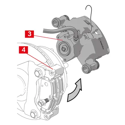
2. Dajte dole ochranné kryty (bod 3) z vodiacich puzdier.
3. Ak má uzáver lem (bod 4), odlomte uzáver potiahnutím za lem (bod 4) prstami.
4. Ak je uzáver vyrobený z tvrdého plastu (bod 5), vypáčte ho skrutkovačom. Uzáver sa pri odstránení zlomí.
VAROVANIE! Demontovaný tvrdý plastový uzáver znova nepoužívajte.
UPOZORNENIE! Vodiace puzdro na demontáž musí byť také, ktoré umožňuje otáčať telesom strmeňa bez toho, aby došlo k natiahnutiu prívodného vedenia brzdovej kvapaliny.
VAROVANIE! Sú dva typy vodiacich puzdier:
- so samostatnou skrutkou
- so zabudovanou skrutkou
5. Pomocou kľúča uvoľnite a úplne vytiahnite skrutku (bod 6) alebo zabudované vodiace puzdro (bod 7)
VAROVANIE! Ak sú na strmeni prilepené brzdové doštičky, odlepte ich pomocou skrutkovača.
NEBEZPEČENSTVO! Pri otvorení telesa strmeňa sa môžu roztiahnuť pružiny znižujúce zvyškový krútiaci moment.
6. V prípade nezabudovaného vodiaceho puzdra (bod 8) vytiahnite vodiace puzdro z držiaka strmeňa (bod 9) a vypáčte ho zo sedla skrutkovačom.
7. Pri výmene strmeňa na zadných kolesách s odpružením a listovými pružinami sa musia demontovať obe vodiace puzdrá (bod 8), aby sa teleso strmeňa (bod 10) úplne oddelilo od držiaka strmeňa (bod 9).

8. Odtiahnite teleso strmeňa (bod 10) z držiaka strmeňa (bod 9) jeho otáčaním okolo druhého vodiaceho puzdra, kým sa doštičky nevysunú z držiaka strmeňa. Pripevnite teleso strmeňa k podvozku vozidla pomocou vhodných podpier.
9. Vyberte doštičky (bod 11) a pružiny (bod 12) tak, aby ste nič nepoškodili a mohli ste ich znova namontovať na nový strmeň.
10. Na označenie smeru otáčania kotúča na doštičkách použite značku, aby ste sa vyhli ich nesprávnej opätovnej montáži.
11. Ak sú pružiny znižujúce zvyškový krútiaci moment (bod 13) stále na svojom mieste, vyberte ich.
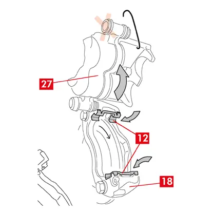
12. Umiestnite rozperu (bod 14) do priestoru pre cestujúcich medzi sedadlo a brzdový pedál, aby pedál zostal počas tejto práce stlačený.
VAROVANIE! Vďaka tomu je brzdový hydraulický okruh uzavretý, čím sa zabráni úniku brzdovej kvapaliny.
UPOZORNENIE! Počas všetkých ďalej opísaných fáz dbajte na to, aby sa brzdová kvapalina nedostala do kontaktu s časťami vozidla, ktoré by sa mohli poškodiť, najmä s lakovanými časťami. Prípadné náhodné postriekanie alebo únik brzdovej kvapaliny okamžite utrite kuchynskou utierkou a očistite vodou.
13. Uvoľnite prívodné potrubie (bod 15) na strmeni natoľko, aby ste ho mohli úplne odskrutkovať rukou, ale zabráňte úniku brzdovej kvapaliny.
14. Vidlicovým kľúčom odskrutkujte upevňovacie skrutky (bod 16) a vyberte držiak strmeňa (bod 9) z držiaka náboja.
15. Úplne odpojte prívodné vedenie (bod 15) od telesa strmeňa.
16. Okamžite zotrite prípadný únik brzdovej kvapaliny.
17. Držte prívodné vedenie v zdvihnutej polohe, aby ste zabránili úniku kvapaliny.
18. V prípade strmeňov so zabudovanou parkovacou brzdou odpojte koncovku kábla parkovacej brzdy od jej sedla na strmeni.
19. Vytiahnite strmeň, ktorý sa má vymeniť.
20. Očistite brzdové plochy (bod 17) na kotúči pomocou odmasťovacieho prípravku (napr. rozpúšťadlo SE47).
Postup montáže strmeňa
UPOZORNENIE! Nedemontujte ochranný uzáver z otvoru prívodu kvapaliny na novom strmeni, kým k nemu nepripojíte prívodné vedenie.
Pred montážou nového strmeňa namažte puzdrá a prachové kryty dodaným mazivom.
VAROVANIE! EUH210 – Karta bezpečnostných údajov je k dispozícii na požiadanie.
VAROVANIE! EUH208 – obsahuje N-alkylovaný benzotriazol. Môže spôsobiť alergickú reakciu.
1. Zložte ochranné uzávery z puzdier, ak sú nasadené.
2. Uvoľnite skrutky alebo vodiace puzdrá pomocou zabudovanej skrutky.
3. V prípade samostatných skrutiek ich úplne vytiahnite.
4. Odtiahnite teleso strmeňa od podpery strmeňa.
VAROVANIE! S cieľom zamedziť poškodeniu prachových krytov vytiahnite puzdrá zo strany krytu.
5. Odstráňte kryty.
6. Dôkladne očistite všetky montované komponenty, miesta uloženia puzdier a miesta uloženia krytov pomocou vhodných prostriedkov (napr. vlhkou handričkou).
7. Očistite montážne plochy na držiaku náboja.

8. Vložte nový držiak strmeňa (bod 18) do kotúča.
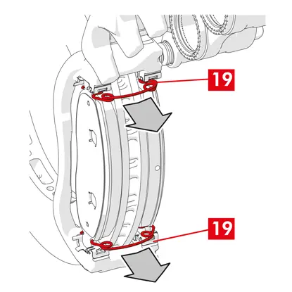
9. Vložte a priblížte dve upevňovacie skrutky (body 19 a 20).
10. Utiahnite upevňovaciu skrutku na vstupnej strane kotúča (bod 19) (pri zaradenom prevodovom stupni dopredu) použitím uťahovacieho momentu odporúčaného výrobcom vozidla.
11. Utiahnite druhú upevňovaciu skrutku 20 (na strane výstupu kotúča) použitím uťahovacieho momentu odporúčaného výrobcom vozidla.
Použite nasledujúce odporúčané uťahovacie momenty:
| Typ skrutky | Uťahovací moment |
| M12x1,25 | 115 Nm |
| M12x1,5 | 125 Nm |
| M14x1,5 | 180 Nm |
| M16x1,5 | 210 Nm |
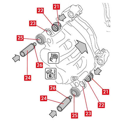
12. Rovnomerne namažte celý vnútorný povrch krytov (bod 21) a kontaktný profil (bod 22) s telesom strmeňa.
13. Vložte kryty (bod 21) na miesta uloženia (bod 23) na tele strmeňa.
UPOZORNENIE! Prstom skontrolujte, či je kryt vložený a správne usadený v tele strmeňa.
14. Namažte vonkajší povrch puzdier (bod 24) a ich miesta uloženia (bod 25) v tele strmeňa, vložte puzdrá do telesa strmeňa zo strany oproti krytu.
15. Zatlačte puzdrá (bod 24), kým kryty (bod 21) nezapadnú na miesto ich uloženia (bod 26).
16. Odstráňte prebytočný tuk.
17. Nasaďte teleso strmeňa na držiak strmeňa prevlečením a naskrutkovaním skrutky alebo zabudovaného puzdra na výstupnej strane kotúča (pri zaradenom prevodovom stupni dopredu).
18. Odtiahnite teleso strmeňa (bod 27) z držiaka strmeňa (bod 18) jeho otáčaním okolo vodiaceho puzdra, kým doštičky nezapadnú do držiaka strmeňa. Pripevnite teleso strmeňa k podvozku vozidla pomocou vhodných podpier.
UPOZORNENIE! Nepoužívajte miesto uloženia vodiaceho puzdra ako upevňovací bod.
Montáž doštičiek
1. V prípade potreby namontujte bočné pružiny (bod 12) do držiaka strmeňa a vyvíjajte správny tlak, aby ste ich riadne pripevnili.
2. V prípade strmeňov so štyrmi pružinami vždy namontujte pružiny tak, aby perá smerovali von z držiaka strmeňa.
UPOZORNENIE! Dodržiavajte správny smer montáže.
VAROVANIE! V prípade prítomnosti doštičiek s lepiacou stranou je potrebné namontovať nové doštičky; postupujte podľa pokynov dodaných s náhradnými doštičkami.
UPOZORNENIE! Doštička s indikátorom opotrebenia sa musí namontovať späť do polohy, v ktorej bola pôvodne pred demontážou.
3. Namontujte späť brzdové doštičky (bod 11) do držiaka strmeňa (bod 18); pri strmeňoch typu B pomocou skrutkovača vypáčte bočné pružiny (bod 12).
VAROVANIE! Všetky šípky vyrazené na doštičkách musia ukazovať v smere otáčania kotúča.
NEBEZPEČENSTVO! Doštičky musia byť vložené tak, aby bol trecí materiál otočený ku kotúču.
VAROVANIE! Všetky šípky vyrazené na doštičkách musia ukazovať v smere otáčania kotúča.
NEBEZPEČENSTVO! Doštičky musia byť vložené tak, aby bol trecí materiál otočený ku kotúču.
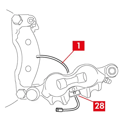
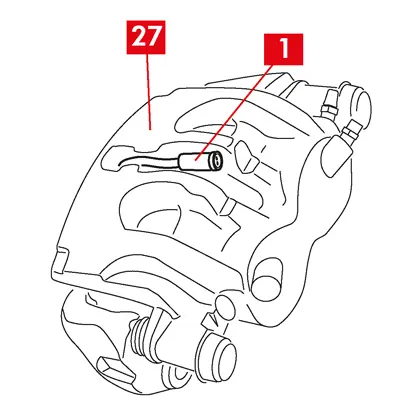
4. Kábel indikátora opotrebenia (bod 1) prevlečte cez určený kanál takto:
Pri strmeňoch typu A – cez pružinu (bod 28).
Pri strmeňoch typu B – cez teleso strmeňa (bod 27).
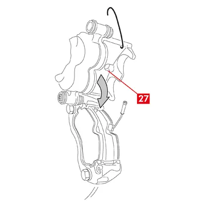
4. Opatrne zatvorte strmeň otočením telesa strmeňa (bod 27) okolo naskrutkovaného vodiaceho puzdra. Pri prípadných doštičkách s lepiacou stranou dávajte pozor, aby sa teleso strmeňa nedotklo doštičky, kým nedokončíte montáž telesa strmeňa.
UPOZORNENIE! Opatrne zatvorte strmeň a dajte pozor, aby sa ochranné kryty puzdier nepoškodili nárazom o držiak strmeňa.
UPOZORNENIE! Opatrne zatvorte strmeň a dajte pozor, aby sa ochranné kryty puzdier nepoškodili nárazom o držiak strmeňa.
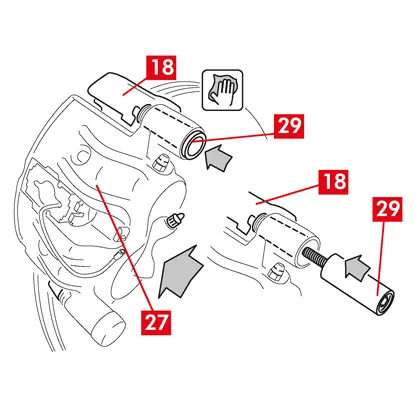
5. Posuňte teleso strmeňa (bod 27) smerom k držiaku strmeňa (bod 18).
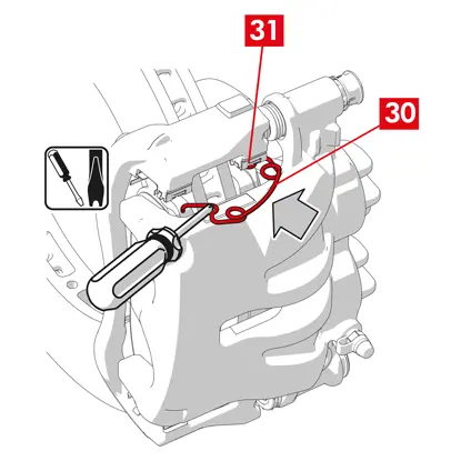
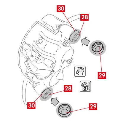
6. Vložte naspäť vodiace puzdro (bod 29) na miesto uloženia držiaka strmeňa.
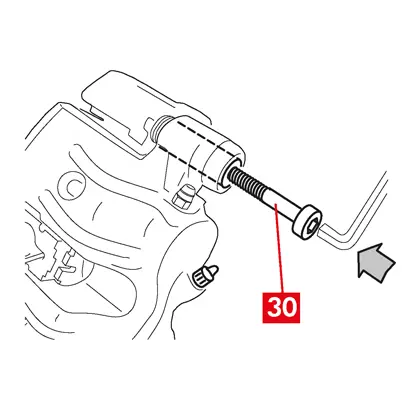
7. Vložte a zaskrutkujte novú skrutku (bod 30), ak je prítomná.
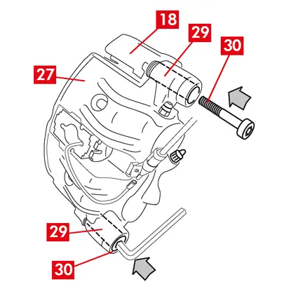
8. Pri výmene strmeňa na zadných kolesách s odpružením a listovými pružinami sa musí teleso strmeňa (bod 27) znovu nasadiť na držiak strmeňa (bod 18), potom znova nasadiť obe vodiace puzdrá (bod 29) a zasunúť a utiahnuť dve nové skrutky (bod 30), ak sú prítomné.
9. Ak ešte nie sú zaskrutkované, utiahnite upevňovaciu skrutku vodiaceho puzdra alebo zabudované vodiace puzdro na strane vstupu do kotúča (pri zaradenom prevodovom stupni dopredu). Potom rovnakým momentom utiahnite druhú skrutku alebo druhé zabudované vodiace puzdro.
10. Utiahnite uťahovacím momentom uvedeným v tabuľke nižšie:
| Typ | Uťahovací moment | |
| Uťahovacia skrutka | (M8 – CH6) | 32 ÷ 36 Nm |
| Vodiace puzdro so zabudovanou skrutkou | (M8 – CH6) | 32 ÷ 36 Nm |
| Vodiace puzdro so zabudovanou skrutkou | (M10 – CH8) | 65 ÷ 75 Nm |
NEBEZPEČENSTVO! Dodržujte opísanú postupnosť uťahovania; jeho nedodržanie by mohlo ohroziť správnu funkciu strmeňa.
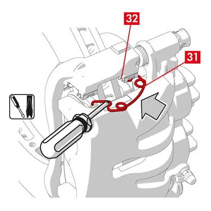
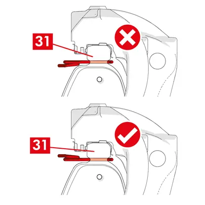
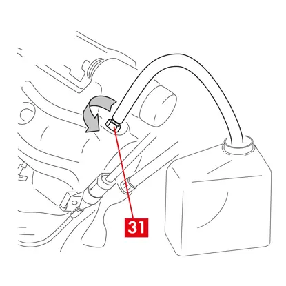
11. V prípade pružín znižujúcich zvyškový krútiaci moment (bod 31) zaháknite pružinu pod plochou (bod 32) doštičky a pomocou skrutkovača s dutým hrotom zaháknite spodnú stranu plochy na druhej doštičke.
NEBEZPEČENSTVO! Nesprávne pripevnenie pružiny môže spôsobiť jej otvorenie.
UPOZORNENIE! Dodržiavajte správny smer montáže.
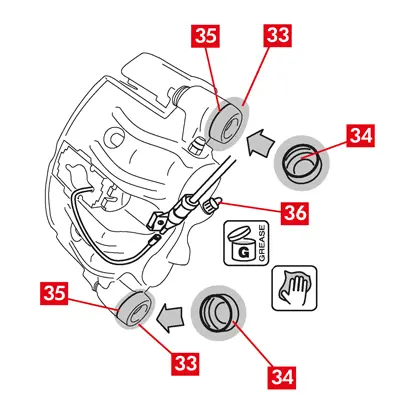
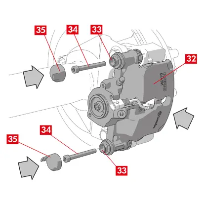
12. Dôkladne očistite diely (bod 33), aby zostali na svojom mieste, a nasaďte nové ochranné uzávery (bod 34), pričom ich vnútorný povrch a miesto uloženia telesa strmeňa namažte mazivom, ktoré je súčasťou súpravy náhradných dielov.
13. Otočte ochranný kryt (bod 34) tak, aby dokonale priliehal na miesto uloženia (bod 35).
14. V prípade prítomnosti indikátora opotrebenia ho pripojte naspäť k svorke vo vozidle a zaistite ho k podložke na strmeni a zaistite všetky príchytky na podvozku.
15. Demontujte ochranný kryt z otvoru na prívod brzdovej kvapaliny (bod 36).
16. Pripojte naspäť prívodné vedenie brzdovej kvapaliny.
17. Vyberte rozperu, ktorú ste predtým vložili do priestoru pre cestujúcich, čím uvoľníte pedál z brzdy a opätovne otvoríte hydraulický okruh.
18. Otvorte uzáver nádržky brzdovej kvapaliny.

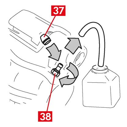
19. Demontujte ochranný uzáver (bod 37) a na odvzdušňovaciu zátku (bod 38) na strmeni pripojte priehľadnú hadičku, ktorej koniec vložte do nádoby na zachytávanie prípadnej kvapaliny.
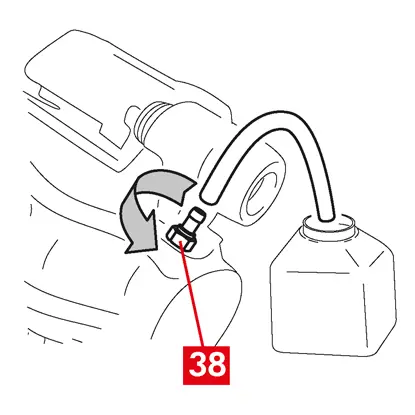
20. Otvorte odvzdušňovaciu zátku (bod 38).
21. Opakovane stláčajte brzdový pedál vozidla, kým z odvzdušňovacej zátky nezačne vytekať brzdová kvapalina.
22. Podržaním pedálu zatvorte odvzdušňovaciu zátku. Uvoľnite pedál, počkajte niekoľko sekúnd, potom postup opakujte, kým nebude vytekať kvapalina bez vzduchových bublín a kým sa neobnoví obvyklý odpor a zdvih brzdového pedála.
23. Odvzdušňovaciu zátku utiahnite uťahovacím momentom uvedeným v tabuľke:
| Odvzdušňovacia zátka | M6x1 | M8x1,25 | M10x1 | M12x1 |
| Uťahovací moment | 5÷7 Nm | 7÷10 Nm | 17÷20 Nm | 18÷22 Nm |
24. Demontujte priehľadnú hadičku a nasaďte ochranný uzáver na odvzdušňovaciu zátku.
25. Zopakujte postup odvzdušňovania na všetkých ostatných odvzdušňovacích zátkach.
26. Po odvzdušnení úplne stiahnite piesty v strmeni pomocou vhodného nástroja (napr. sťahováka) a potom doplňte hladinu kvapaliny podľa odporúčania výrobcu.
27. Zatvorte uzáver nádržky brzdovej kvapaliny.
28. Pri naštartovanom motore silno stlačte brzdový pedál vozidla a skontrolujte, či nedochádza k úniku kvapaliny zo strmeňa alebo k abnormálnym poklesom tlaku v okruhu a či sa rozsvietia zadné brzdové svetlá.
NEBEZPEČENSTVO! Ak kvapalina uniká zo strmeňa, zopakujte všetky kroky uvedené v tomto dokumente, aby ste určili príčinu a odstránili problém.
29. V prípade strmeňov so zabudovanou parkovacou brzdou pripojte koncovku kábla parkovacej brzdy k jej sedlu na strmeni.
30. Opakovane zatiahnite a uvoľnite parkovaciu brzdu v kabíne.
31. Namontujte naspäť koleso.
32. Ak sú brzdové doštičky nové, zabehnite ich; postupujte podľa pokynov dodaných s náhradnými doštičkami.
Tieto inštrukcie poskytujú pokyny na výmenu komponentov pre plávajúce strmene úžitkových vozidiel (typ ECS53 a ECS60) so zabudovaným elektrickým parkovacím mechanizmom:
1. Jednotka pohonu
2. Doštičky
3. Teleso strmeňa (bez doštičiek a držiaka strmeňa)
4. Držiak strmeňa
2. Doštičky
3. Teleso strmeňa (bez doštičiek a držiaka strmeňa)
4. Držiak strmeňa
VAROVANIE! Pred výmenou náhradných dielov z balenia si prečítajte tento dokument. Vykonajte iba kroky potrebné na výmenu náhradného dielu alebo dielov z balenia.
Postup výmeny
Pred začatím výmeny sa uistite, že náhradné diely sú vhodné pre výmenu pre danú značku a model vozidla.
VAROVANIE! V prípade elektrickej poruchy demontujte jednotku pohonu a potiahnite piest späť, pričom pomocou vhodného kľúča otočte skrutku Torx v smere hodinových ručičiek.
- Poznamenajte si polohu všetkých čiastočne alebo úplne demontovaných komponentov pre správnu spätnú montáž.
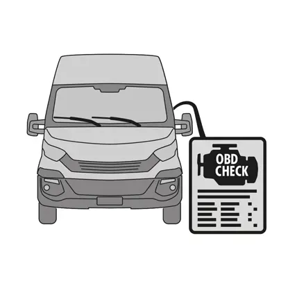
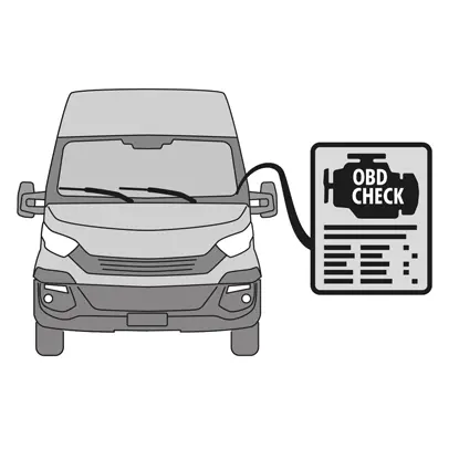
1. Pripojte diagnostický nástroj (palubná diagnostika – OBD) k vozidlu a prepnite ho do režimu údržby podľa pokynov výrobcu vozidla.
UPOZORNENIE! Skontrolujte, či je náhradný diel kompatibilný so softvérom vozidla.
2. Odstráňte koleso.

3. Uvoľnite prívodný kábel jednotky pohonu z káblovej priechodky.
4. V prípade strmeňa typu ECS60 uvoľnite a vyberte káblovú priechodku (bod 5).
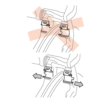
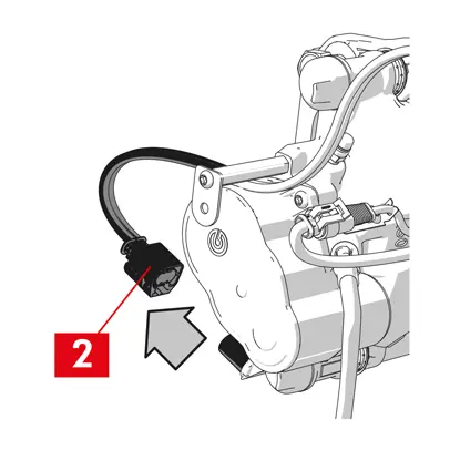
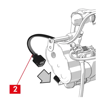
5. Odpojte kábel elektrického napájania (bod 6) od jednotky pohonu.
VAROVANIE! Konektor môže mať bezpečnostnú západku.
VAROVANIE! Konektor môže mať bezpečnostnú západku.
Demontáž jednotky pohonu
VAROVANIE! Pokračujte v demontáži jednotky pohonu len vtedy, ak máte k dispozícii samostatný náhradný diel.
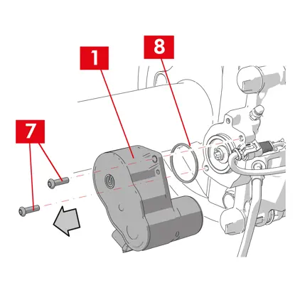
1. Uvoľnite upevňovacie skrutky (bod 7) z jednotky pohonu (bod 1).
2. Demontujte jednotku pohonu (bod 1).
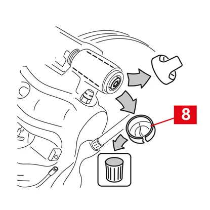
3. Demontujte tesnenie (bod 8).
Demontáž doštičiek
UPOZORNENIE! Nepoškoďte žiadne komponenty, ktoré chcete znovu použiť.
NEBEZPEČENSTVO! Nenaťahujte prívodné vedenie brzdovej kvapaliny.
NEBEZPEČENSTVO! Nenaťahujte prívodné vedenie brzdovej kvapaliny.
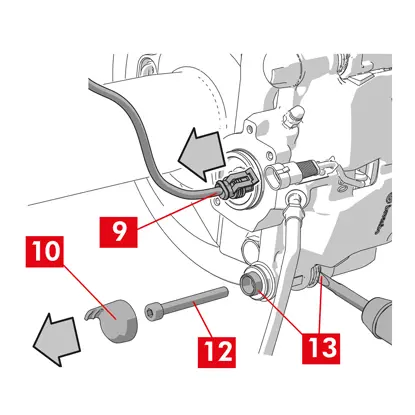
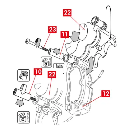
1. V prípade prítomnosti indikátora opotrebenia (bod 9) ho odpojte od svorky vo vozidle a uvoľnite ho z podložky, ktorá ho upevňuje k strmeňu, a zo všetkých príchytiek na podvozku.
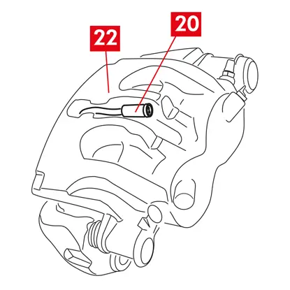
2. Demontujte ochranný uzáver (bod 10) zo sekundárneho puzdra (výstupná strana kotúča otáčania pohonu dopredu).
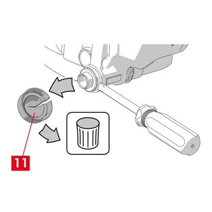
3. Ak je uzáver vyrobený z tvrdého plastu (bod 11), vypáčte ho skrutkovačom. Uzáver sa pri odstránení zlomí.
VAROVANIE! Demontovaný tvrdý plastový uzáver znova nepoužívajte.
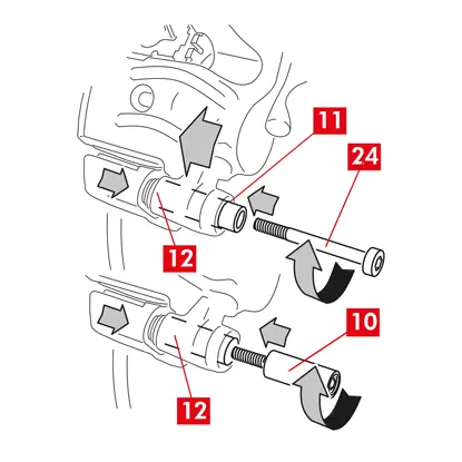
4. Uvoľnite a odstráňte druhotnú skrutku (bod 12).
5. V prípade strmeňa typu ECS60 použite skrutkovač na vypáčenie puzdra z drážky, aby ste ho uvoľnili z držiaka strmeňa.
6. Demontujte ochranný uzáver (bod 14) z primárneho puzdra (vstupná strana kotúča otáčania pohonu dopredu).
7. Úplne uvoľnite primárnu skrutku (bod 15) a vyberte ju.
VAROVANIE! Pomocou skrutkovača vypáčte vodiace puzdrá z drážok.
8. Vyberte primárne vodiace puzdro (bod 16) natoľko, aby ste ho uvoľnili z držiaka strmeňa.
9. Odtiahnite teleso strmeňa (bod 3) z držiaka strmeňa (bod 4), pričom dávajte pozor, aby sa nenatiahlo prívodné vedenie brzdovej kvapaliny.
10. Pripevnite teleso strmeňa k podvozku vozidla pomocou vhodných podpier.
UPOZORNENIE! Nepoužívajte miesto uloženia puzdra ako upevňovací bod
11. Vyberte doštičky (bod 17) a pružiny (bod 18) tak, aby ste nič nepoškodili a mohli ste ich znova namontovať na nový strmeň.
12. Ak sú pružiny znižujúce zvyškový krútiaci moment (bod 19) stále na svojom mieste, vyberte ich.
VAROVANIE! Pre správnu opätovnú montáž tých istých doštičiek nakreslite fixkou niekoľko šípok (ak nie sú k dispozícii) na doštičkách, aby ste označili smer otáčania kotúča.
Demontáž telesa strmeňa
1. Umiestnite rozperu (bod 20) do priestoru pre cestujúcich medzi sedadlo a brzdový pedál, aby pedál zostal počas tejto práce stlačený.
VÝSTRAHA! Vďaka tomu je brzdový hydraulický okruh uzavretý, čím sa zabráni úniku brzdovej kvapaliny.
UPOZORNENIE! Počas všetkých ďalej opísaných fáz dbajte na to, aby sa brzdová kvapalina nedostala do kontaktu s časťami vozidla, ktoré by sa mohli poškodiť, najmä s lakovanými časťami. Prípadné náhodné postriekanie alebo únik brzdovej kvapaliny okamžite utrite kuchynskou utierkou a očistite vodou.
2. Uvoľnite prívodné potrubie (bod 21) na strmeni natoľko, aby ste ho mohli úplne odskrutkovať rukou, ale zabráňte úniku brzdovej kvapaliny.
3. Úplne odpojte prívodné vedenie (bod 21) od telesa strmeňa.

4. Okamžite zotrite prípadný únik brzdovej kvapaliny.
5. Držte prívodné vedenie v zdvihnutej polohe, aby ste zabránili úniku kvapaliny.
6. Odtiahnite teleso strmeňa (bod 3).
Demontáž držiaka strmeňa
UPOZORNENIE! Počas demontáže držte držiak strmeňa na mieste, aby náhodu nespadol.
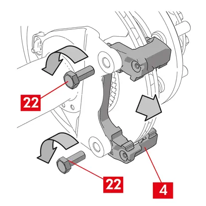
1. Uvoľnite upevňovacie skrutky (bod 22).
2. Demontujte držiak strmeňa (bod 4) z držiaka náboja.
Postup montáže
Namontujte naspäť nové náhradné diely.
1. Dôkladne očistite všetky montované komponenty (či už nové alebo predtým demontované), miesta uloženia puzdier a miesta uloženia pružiny pomocou vhodných prostriedkov (napr. vlhkou handričkou).
NEBEZPEČENSTVO! Skontrolujte, či sú komponenty neporušené, v prípade poškodenia ich nahraďte novými.
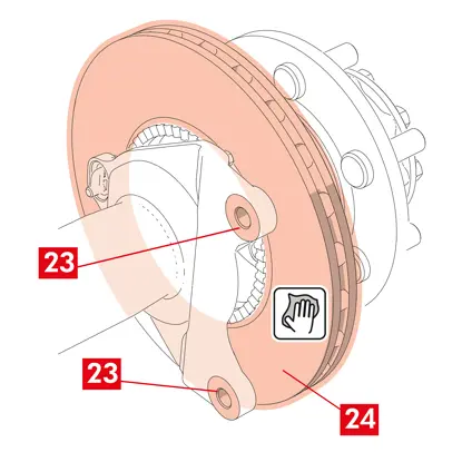
2. Očistite montážne plochy (bod 23) na držiaku náboja.
3. Očistite brzdové plochy (bod 24) na kotúči pomocou odmasťovacieho prípravku (napr. rozpúšťadlo SE47).
Montáž držiaka strmeňa
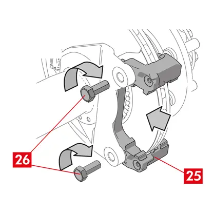
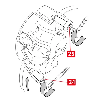
1. Umiestnite nový držiak strmeňa (bod 25) na držiak náboja.
2. Vložte a utiahnite upevňovacie skrutky (bod 26) uťahovacím momentom odporúčaným výrobcom vozidla.
Montáž doštičiek a tela strmeňa
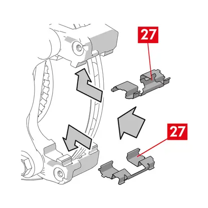
1. Vložte naspäť pružiny (bod 27) a umiestnite ich správnym smerom na miesta ich uloženia.
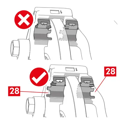
2. V prípade strmeňa typu ECS52 so štyrmi pružinami vždy namontujte pružiny tak, aby perá (bod 28) smerovali von z držiaka strmeňa.
VAROVANIE! V prípade prítomnosti doštičiek s lepiacou stranou je potrebné namontovať nové doštičky; postupujte podľa pokynov dodaných s náhradnými doštičkami.
UPOZORNENIE! Doštička s indikátorom opotrebenia sa musí namontovať späť do polohy, v ktorej bola pôvodne pred demontážou.
NEBEZPEČENSTVO! Doštičky musia byť vložené tak, aby bol trecí materiál otočený ku kotúču.
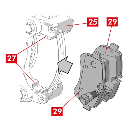
3. Namontujte späť brzdové doštičky (bod 29) do držiaka strmeňa (bod 25); pomocou skrutkovača vypáčte bočné pružiny (bod 27).
4. V prípade pružín znižujúcich zvyškový krútiaci moment (bod 30) zaháknite pružinu pod plochou (bod 31) doštičky a pomocou skrutkovača s dutým hrotom zaháknite spodnú stranu plochy na druhej doštičke.
NEBEZPEČENSTVO! Nesprávne pripevnenie pružiny môže spôsobiť jej otvorenie.
NEBEZPEČENSTVO! Nesprávne pripevnenie pružiny môže spôsobiť jej otvorenie.
UPOZORNENIE! Dodržiavajte správny smer montáže.
UPOZORNENIE! Ak je teleso strmeňa nové, nedemontujte ochranný uzáver z otvoru prívodu kvapaliny na novom strmeni, kým k nemu nepripojíte prívodné vedenie.
6. Vložte teleso strmeňa (bod 32) do kotúča tak, aby sa vodiace puzdrá zhodovali s otvormi na držiaku strmeňa.
UPOZORNENIE! Nepoškoďte kryty.
7. Zatlačte vodiace puzdrá (bod 33) na miesta ich uloženia na držiaku strmeňa.
8. Vložte a utiahnite skrutky (bod 34) uťahovacím momentom 32 ÷ 36 Nm.
9. Vložte uzávery (bod 35).
UPOZORNENIE! Pred demontážou ochranného uzáveru nechajte prívodný bod čo najvyššie a zabezpečte, aby z vnútra strmeňa nevytiekla žiadna brzdová kvapalina.
10. V prípade prítomnosti kábla indikátora opotrebenia ho pripojte naspäť k svorke vo vozidle a zaistite ho k podložke na strmeni, ak je prítomný, a zaistite všetky príchytky na podvozku.
Pripojenie prívodného vedenia brzdovej kvapaliny
1. Demontujte ochranný kryt (bod 36) z otvoru na prívod brzdovej kvapaliny.
2. Pripojte naspäť prívodné vedenie brzdovej kvapaliny (bod 21).
3. Vyberte rozperu, ktorú ste predtým vložili do priestoru pre cestujúcich, čím uvoľníte pedál z brzdy a opätovne otvoríte okruh.
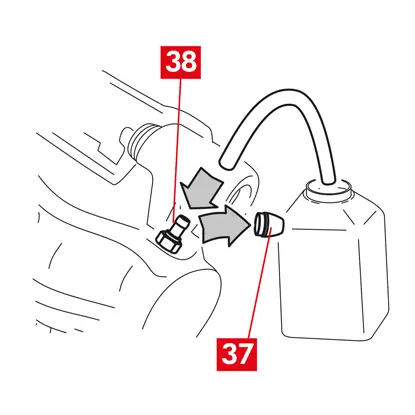
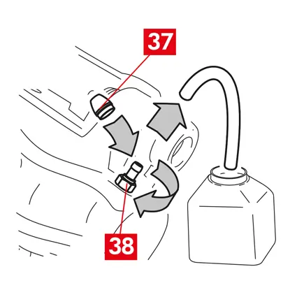
4. Demontujte ochranný kryt (bod 37) z odvzdušňovacej zátky (bod 38).
5. Pripojte priehľadnú hadičku k odvzdušňovacej zátke (bod 38) na strmeni a jej koniec vložte do nádoby na zachytávanie prípadnej kvapaliny.
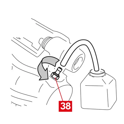
6. Otvorte odvzdušňovaciu zátku (bod 38).
7. Opakovane stláčajte brzdový pedál vozidla, kým z odvzdušňovacej zátky nezačne vytekať brzdová kvapalina.
8. Podržaním pedálu zatvorte odvzdušňovaciu zátku. Uvoľnite pedál, počkajte niekoľko sekúnd, potom postup opakujte, kým nebude vytekať kvapalina bez vzduchových bublín a kým sa neobnoví obvyklý odpor a zdvih brzdového pedála.
9. Odvzdušňovaciu zátku (bod 38) utiahnite uťahovacím momentom uvedeného v nasledujúcej tabuľke:
| Typ odvzdušňovača | M10x1 |
| Uťahovací moment | 12÷16 Nm |
10. Demontujte priehľadnú hadičku.
11. Zopakujte postup odvzdušňovania na všetkých ostatných odvzdušňovacích zátkach.
12. Namontujte naspäť ochranný uzáver (bod 37).
13. Po odvzdušnení úplne stiahnite piesty v strmeni pomocou vhodného nástroja (napr. sťahováka) a potom doplňte hladinu kvapaliny podľa odporúčania výrobcu.
14. Pri naštartovanom motore silno stlačte brzdový pedál vozidla a skontrolujte, či nedochádza k úniku kvapaliny zo strmeňa alebo k abnormálnym poklesom tlaku v okruhu a či sa rozsvietia zadné brzdové svetlá.
NEBEZPEČENSTVO! Ak kvapalina uniká zo strmeňa, zopakujte všetky kroky uvedené v tomto dokumente, aby ste určili príčinu a odstránili problém.
Montáž jednotky pohonu
VAROVANIE! Jednotka pohonu môže byť dodaná už namontovaná na tele strmeňa.
Namontujte naspäť nové náhradné diely.
- Pred opätovnou montážou vyčistite všetky komponenty, ktoré ste predtým demontovali.
UPOZORNENIE! Vždy používajte nové skrutky so zaisťovačom závitu. Vždy nasaďte nové tesnenie.
NEBEZPEČENSTVO! Skontrolujte, či sú komponenty neporušené, v prípade poškodenia ich nahraďte novými
1. Vyčistite kontaktnú plochu na strmeni a na jednotke pohonu.
2. Vyčistite všetky zvyšky zaisťovača závitov z miest uloženia závitových skrutiek.
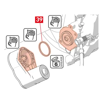
3. Vyčistite a namažte tesnenie (bod 39) dodaným mazivom.
4. Namažte vnútorný priemer spojky jednotky pohonu dodaným mazivom.
VAROVANIE! EUH210 – Karta bezpečnostných údajov je k dispozícii na požiadanie.
VAROVANIE! EUH208 – obsahuje N-alkylovaný benzotriazol. Môže spôsobiť alergickú reakciu.
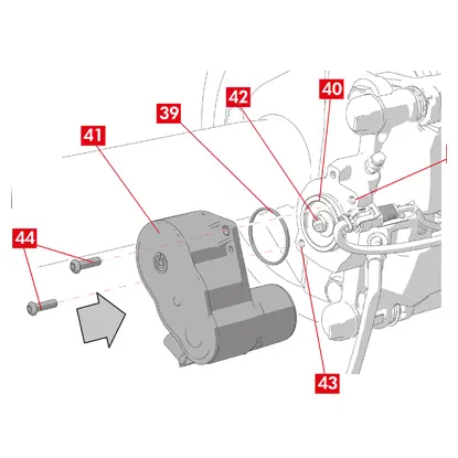
5. Vložte tesnenie (bod 39) na miesto jeho uloženia (bod 40) na telese strmeňa.
6. Nasaďte jednotku pohonu (bod 41) na skrutku Torx (bod 42) na telese strmeňa.
7. Otočte jednotku pohonu (bod 41) tak, aby sa otvory (bod 43) upevňovacích skrutiek (bod 44) zhodovali s ich pôvodnou montážnou polohou.
UPOZORNENIE! Pri montáži jednotky pohonu na teleso strmeňa sa nestlačte tesnenie (bod 39).
8. Vložte a utiahnite upevňovacie skrutky (bod 44) uťahovacím momentom 7 ÷ 10 Nm.
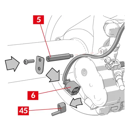
9. Demontujte ochranný kryt (bod 45), ak je prítomný, a pripojte elektrický napájací kábel (bod 6).
10. Naskrutkujte káblovú priechodku (bod 5) na miesto, kde ste predtým vybrali.
11. Upevnite prívodný kábel jednotky pohonu (bod 6) na káblovú priechodku (bod 5).
Záverečné fázy
1. Namontujte naspäť koleso.
2. Vykonajte postup resetovania (kontrola montáže).
3. V prípade potreby vynulujte počítadlá (reset interných počítadiel) podľa predpisu výrobcu vozidla.
4. Ak to vyžaduje výrobca vozidla, zabehnite doštičky.
5. Odpojte diagnostické zariadenie. (Palubná diagnostika – OBD).
Tieto inštrukcie obsahujú návod na výmenu telesa strmeňa pre plávajúce strmene s 2 alebo 4 bočnými pružinami a pružinami znižujúcimi zvyškový krútiaci moment.
Pri výmene len upevňovacích skrutiek sa riaďte len príslušnými časťami.
Postup výmeny
Pred začatím výmeny sa uistite, že náhradné diely sú vhodné pre výmenu pre danú značku a model vozidla.
- Poznamenajte si polohu všetkých čiastočne alebo úplne demontovaných komponentov pre správnu spätnú montáž.
- Odstráňte koleso.
Pre strmene ECS
VAROVANIE! V prípade elektrickej poruchy demontujte jednotku pohonu (bod 5) a potiahnite piest späť, pričom pomocou vhodného kľúča otočte skrutku Torx v smere hodinových ručičiek
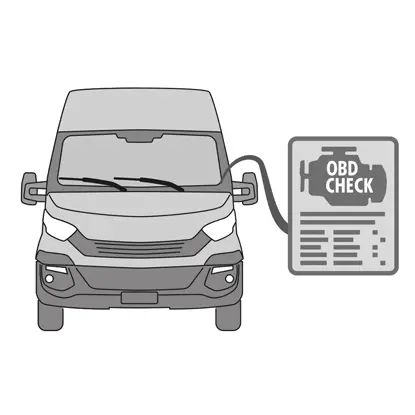
1. Pripojte diagnostický nástroj (palubná diagnostika – OBD) k vozidlu a prepnite ho do režimu údržby podľa pokynov výrobcu vozidla.
UPOZORNENIE! Bez vykonania tejto operácie nie je možné piest stiahnuť späť pomocou sťahováka alebo iného vhodného nástroja.
UPOZORNENIE! Skontrolujte, či je náhradný diel kompatibilný so softvérom vozidla.
2. Odpojte kábel elektrického napájania (bod 2) od jednotky pohonu.
VAROVANIE! Konektor môže mať bezpečnostnú západku.
Na všetky druhy strmeňov
1. Pri strmeňoch s parkovacou brzdou odpojte ovládacie lanko (bod 3) od strmeňa.
2. V prípade prítomnosti indikátora opotrebenia (bod 4) ho odpojte od svorky vo vozidle a uvoľnite ho z podložky (bod 5), ktorá ho upevňuje k strmeňu, a zo všetkých príchytiek na podvozku.

3. Dajte dole ochranné kryty (bod 6) z vodiacich puzdier.
4. Ak má uzáver lem (bod 7), odlomte uzáver potiahnutím za lem (bod 7) prstami.
5. Ak je uzáver vyrobený z tvrdého plastu (bod 8), vypáčte ho skrutkovačom. Uzáver sa pri odstránení zlomí.
VAROVANIE! Demontovaný tvrdý plastový uzáver znova nepoužívajte.
UPOZORNENIE! Vodiace puzdro na demontáž musí byť také, ktoré umožňuje otáčať telesom strmeňa bez toho, aby došlo k natiahnutiu prívodného vedenia brzdovej kvapaliny.
VAROVANIE! Sú dva typy vodiacich puzdier: so samostatnou skrutkou, so zabudovanou skrutkou.
6. Pomocou kľúča uvoľnite a úplne vytiahnite skrutku (bod 9) alebo zabudované vodiace puzdro (bod 10).
7. V prípade nezabudovaného vodiaceho puzdra (bod 11) vytiahnite vodiace puzdro z držiaka strmeňa (bod 12) a vypáčte ho zo sedla skrutkovačom.
8. Pri výmene strmeňa na zadných kolesách s odpružením a listovými pružinami sa musia demontovať obe vodiace puzdrá 11, aby sa teleso strmeňa (bod 13) úplne oddelilo od držiaka strmeňa (bod 12).
VAROVANIE! Ak sú k strmeňu prilepené brzdové doštičky, oddeľte ich pomocou skrutkovača a dajte pozor, aby ste nepoškodili žiadne gumené časti strmeňa.
NEBEZPEČENSTVO! Pri otvorení telesa strmeňa sa môžu roztiahnuť pružiny znižujúce zvyškový krútiaci moment.
9. Odtiahnite teleso strmeňa (bod 13) z držiaka strmeňa (bod 12) jeho otáčaním okolo druhého vodiaceho puzdra, kým sa doštičky (bod 14) nevysunú z držiaka strmeňa. Pripevnite teleso strmeňa k podvozku vozidla pomocou vhodných podpier. Nepoužívajte miesto uloženia puzdra ako upevňovací bod.
11. Vyberte doštičky (bod 14) tak, aby ste nič nepoškodili.
12. Na označenie smeru otáčania kotúča na doštičkách použite značku, aby ste sa vyhli ich nesprávnej opätovnej montáži.
14. Ak sú pružiny znižujúce zvyškový krútiaci moment (bod 15) stále na svojom mieste, vyberte ich.
15. Umiestnite rozperu (bod 16) do priestoru pre cestujúcich medzi sedadlo a brzdový pedál, aby pedál zostal počas tejto práce stlačený.
VAROVANIE! Vďaka tomu je brzdový hydraulický okruh uzavretý, čím sa zabráni úniku brzdovej kvapaliny.
UPOZORNENIE! Počas všetkých ďalej opísaných fáz dbajte na to, aby sa brzdová kvapalina nedostala do kontaktu s časťami vozidla, ktoré by sa mohli poškodiť, najmä s lakovanými časťami. Prípadné náhodné postriekanie alebo únik brzdovej kvapaliny okamžite utrite kuchynskou utierkou a očistite vodou.
UPOZORNENIE! Počas všetkých ďalej opísaných fáz dbajte na to, aby sa brzdová kvapalina nedostala do kontaktu s časťami vozidla, ktoré by sa mohli poškodiť, najmä s lakovanými časťami. Prípadné náhodné postriekanie alebo únik brzdovej kvapaliny okamžite utrite kuchynskou utierkou a očistite vodou.
16. Uvoľnite prívodné potrubie (bod 17) na strmeni natoľko, aby ste ho mohli úplne odskrutkovať rukou, ale zabráňte úniku brzdovej kvapaliny.
17. Úplne uvoľnite a vytiahnite skrutku (bod 9) alebo zabudované vodiace puzdro (bod 10).
18. V prípade nezabudovaného vodiaceho puzdra (bod 11) vytiahnite vodiace puzdro z držiaka strmeňa (bod 12) a vypáčte ho zo sedla skrutkovačom.
19. Odtiahnite teleso strmeňa (bod 13) z držiaka strmeňa (bod 12), pričom dávajte pozor, aby sa nenatiahlo prívodné vedenie brzdovej kvapaliny.
20. Úplne odpojte prívodné vedenie (bod 17) od telesa strmeňa.
21. Okamžite zotrite prípadný únik brzdovej kvapaliny.
22. Držte prívodné vedenie v zdvihnutej polohe, aby ste zabránili úniku brzdovej kvapaliny.
23. Vytiahnite strmeň, ktorý sa má vymeniť.
24. V prípade strmeňov so zabudovanou parkovacou brzdou odpojte koncovku kábla parkovacej brzdy od jej sedla na strmeni.
25. Očistite brzdové plochy na kotúči pomocou odmasťovacieho prípravku (napr. rozpúšťadlo SE47).
Montáž doštičiek
UPOZORNENIE! V prípade prítomnosti doštičiek s lepiacou stranou je potrebné namontovať nové doštičky; postupujte podľa pokynov dodaných s náhradnými doštičkami.
1.Skontrolujte, či sú pružiny v správnej polohe. V prípade strmeňov so štyrmi pružinami skontrolujte, či sú perá vždy otočené k vonkajšej strane držiaka strmeňa.
UPOZORNENIE! Nesprávne uloženie pružín by mohlo spôsobiť zranenie.
2. Vložte doštičky (bod 14) do držiaka strmeňa (bod 12). Pomocou skrutkovača stlačte bočné pružiny.
VAROVANIE! Všetky šípky vyrazené na doštičkách musia ukazovať v smere otáčania kotúča.
NEBEZPEČENSTVO! Doštičky musia byť vložené tak, aby bol trecí materiál otočený ku kotúču.
UPOZORNENIE! Doštička s indikátorom opotrebenia sa musí namontovať späť do polohy, v ktorej bola pôvodne pred demontážou.
VAROVANIE! Všetky šípky vyrazené na doštičkách musia ukazovať v smere otáčania kotúča.
NEBEZPEČENSTVO! Doštičky musia byť vložené tak, aby bol trecí materiál otočený ku kotúču.
UPOZORNENIE! Doštička s indikátorom opotrebenia sa musí namontovať späť do polohy, v ktorej bola pôvodne pred demontážou.
3. V prípade prítomnosti indikátora opotrebenia (bod 20) pripojte jeho koncovku k doštičke oproti piestom a v prípade potreby ju vymeňte.
UPOZORNENIE! Pri pripájaní koncovky indikátora opotrebenia skontrolujte, či najvyčnievajúcejšia časť smeruje k trecej ploche doštičky.
UPOZORNENIE! Pri pripájaní koncovky indikátora opotrebenia skontrolujte, či najvyčnievajúcejšia časť smeruje k trecej ploche doštičky.
Montáž telesa strmeňa
UPOZORNENIE! Pri strmeňoch s parkovacou brzdou, keď je teleso strmeňa odmontované z brzdového kotúča a/alebo chýbajú brzdové doštičky, nepohybujte piestom ani hydraulicky, ani pomocou páčky, pretože by ste mohli poškodiť pružinu a/alebo spôsobiť únik brzdovej kvapaliny.
1. Na držiaku strmeňa utrite montážne oblasti (bod 21) s telesom strmeňa (miesta uloženia vodidiel) vlhkou handričkou.
UPOZORNENIE! Nepoužívajte prostriedky, ktoré by mohli poškodiť ochranné kryty, ako je nitrotetrachlóretylénové riedidlo, benzín atď.
2. Vyčistite a rovnomerne namažte celý vnútorný povrch krytov, vonkajší povrch vodiacich puzdier a ich miesta uloženia v telese strmeňa.
3. Vložte nové teleso strmeňa (bod 22) a vložte jedno z dvoch vodiacich puzdier (bod 10) na miesto uloženia na držiaku strmeňa (bod 12).
UPOZORNENIE! Nesnímajte ochranný uzáver z otvoru na prívod brzdovej kvapaliny, kým nebude hadička definitívne pripojená.
UPOZORNENIE! Nesnímajte ochranný uzáver z otvoru na prívod brzdovej kvapaliny, kým nebude hadička definitívne pripojená.
4. V prípade nezabudovaného vodiaceho puzdra (bod 11) nasaďte a utiahnite novú skrutku (bod 23).
5. Opatrne zatvorte strmeň otočením telesa strmeňa (bod 22) okolo usadeného vodiaceho puzdra.
UPOZORNENIE! Opatrne zatvorte strmeň a dajte pozor, aby sa ochranné kryty puzdier nepoškodili nárazom o podperu strmeňa. V prípade potreby vymeňte kryty.
VAROVANIE! Pri prípadných doštičkách s lepiacou stranou dávajte pozor, aby sa teleso nedotklo doštičky, kým nedokončíte montáž telesa strmeňa.
6. Prevlečte sondu indikátora opotrebenia (bod 20) cez určený otvor v telese strmeňa (bod 22).
7. Vložte naspäť druhé vodiace puzdro (bod 10) na miesto uloženia držiaka strmeňa (bod 12).
8. V prípade nezabudovaného vodiaceho puzdra (bod 11) nasaďte a utiahnite novú skrutku (bod 24).
UPOZORNENIE! Pri výmene držiaka strmeňa na zadných kolesách s odpružením a listovými pružinami sa musí teleso strmeňa znovu nasadiť na držiak strmeňa, potom znova nasadiť obe vodiace puzdrá a zasunúť a utiahnuť dve nové skrutky.
9. Utiahnite upevňovaciu skrutku vodiaceho puzdra alebo zabudované vodiace puzdro (bod 24) na strane vstupu do kotúča (pri zaradenom prevodovom stupni dopredu). Potom utiahnite druhú skrutku alebo zabudované vodiace puzdro (bod 25) rovnakým momentom.
10. Utiahnite uťahovacím momentom uvedeným v tabuľke nižšie:
| Typ | Uťahovací moment | |
| Uťahovacia skrutka | (M8 – CH6) | 32 ÷ 36 Nm |
| Vodiace puzdro so zabudovanou skrutkou | (M8 – CH6) | 32 ÷ 36 Nm |
| Vodiace puzdro so zabudovanou skrutkou | (M10 – CH8) | 65 ÷ 75 Nm |
NEBEZPEČENSTVO! Dodržujte opísanú postupnosť uťahovania; jeho nedodržanie by mohlo ohroziť správnu funkciu strmeňa.
11. V prípade pružín znižujúcich zvyškový krútiaci moment (bod 26) zaháknite pružinu pod plochou (bod 27) doštičky a pomocou skrutkovača s dutým hrotom zaháknite spodnú stranu plochy na druhej doštičke.
NEBEZPEČENSTVO! Nesprávne pripevnenie pružiny môže spôsobiť jej otvorenie.
UPOZORNENIE! Dodržiavajte správny smer montáže.
12. Dôkladne očistite diel (bod 28), aby zostal na svojom mieste, a nasaďte nové ochranné uzávery (bod 29), pričom ich vnútorný povrch a miesto uloženia telesa strmeňa namažte mazivom, ktoré je súčasťou súpravy náhradných dielov.
VAROVANIE! EUH210 – Karta bezpečnostných údajov je k dispozícii na požiadanie.
VAROVANIE! EUH208 – obsahuje N-alkylovaný benzotriazol. Môže spôsobiť alergickú reakciu.
VAROVANIE! EUH208 – obsahuje N-alkylovaný benzotriazol. Môže spôsobiť alergickú reakciu.
13. Otočte ochranné kryty (bod 29) tak, aby dokonale priliehali na miesto uloženia (bod 30).
14. V prípade prítomnosti indikátora opotrebenia ho pripojte naspäť k svorke vo vozidle a zaistite ho k podložke na strmeni a zaistite všetky príchytky na podvozku.
15. Demontujte ochranný kryt z otvoru na prívod brzdovej kvapaliny.
16. Pripojte naspäť prívodné vedenie brzdovej kvapaliny.
17. Vyberte rozperu, ktorú ste predtým vložili do priestoru pre cestujúcich, čím uvoľníte pedál z brzdy a opätovne otvoríte okruh.
Pre strmene s parkovacou brzdou
UPOZORNENIE! Pred montážou piestu s doštičkami skontrolujte, či sú k dispozícii držiak strmeňa, brzdové doštičky a kotúč.
- Pomocou páky zostavte piest s doštičkami.
UPOZORNENIE! Používanie hydrauliky je povolené len vtedy, keď je piest vzdialený od doštičiek menej ako 1 mm.
Na všetky druhy strmeňov
1. Pripojte priehľadnú hadičku k odvzdušňovacej zátke (bod 31) na strmeni a jej koniec vložte do nádoby na zachytávanie prípadnej kvapaliny.
2. Otvorte odvzdušňovaciu zátku (bod 31).
3. Opakovane stláčajte brzdový pedál vozidla, kým z odvzdušňovacej zátky nezačne vytekať brzdová kvapalina.
4. Podržaním pedálu zatvorte odvzdušňovaciu zátku. Uvoľnite pedál, počkajte niekoľko sekúnd, potom postup opakujte, kým nebude vytekať kvapalina bez vzduchových bublín a kým sa neobnoví obvyklý odpor a zdvih brzdového pedála.
5. Odvzdušňovaciu zátku (bod 31) utiahnite uťahovacím momentom uvedeným v tabuľke:
| Odvzdušňovacia zátka | M6x1 | M8x1,25 | M10x1 | M12x1 |
| Uťahovací moment | 5÷7 Nm | 7÷10 Nm | 17÷20 Nm | 18÷22 Nm |
6. Demontujte priehľadnú hadičku.
7. Zopakujte postup odvzdušňovania na všetkých ostatných odvzdušňovacích zátkach.
8. Po odvzdušnení úplne stiahnite piesty v strmeni pomocou vhodného nástroja (napr. sťahováka) a potom doplňte hladinu kvapaliny podľa odporúčania výrobcu.
9. Zatvorte uzáver nádržky brzdovej kvapaliny.
10. Pri naštartovanom motore silno stlačte brzdový pedál vozidla a skontrolujte, či nedochádza k úniku kvapaliny zo strmeňa alebo k abnormálnym poklesom tlaku v okruhu a či sa rozsvietia zadné brzdové svetlá.
NEBEZPEČENSTVO! Ak kvapalina uniká zo strmeňa, zopakujte všetky kroky uvedené v tomto dokumente, aby ste určili príčinu a odstránili problém.
Pre strmene s parkovacou brzdou
- V prípade prítomnosti indikátora opotrebenia ho pripojte naspäť k svorke vo vozidle a zaistite ho k podložke na strmeni a zaistite všetky príchytky na podvozku.
- Obnovte správne napnutie ovládacieho kábla.
- Opakovane stlačte páku parkovacej brzdy v kabíne vozidla, kým sa neobnoví obvyklý zdvih.
Pre strmene ECS
1. Demontujte ochranný kryt (ak je prítomný) a pripojte elektrický napájací kábel (bod 2).
2. Vykonajte postup resetovania (kontrola montáže).
3. V prípade potreby vynulujte počítadlá (reset interných počítadiel) podľa predpisu výrobcu vozidla.

4. Ak to vyžaduje výrobca vozidla, zabehnite doštičky.
5. Odpojte diagnostické zariadenie (palubná diagnostika – OBD).
Na všetky druhy strmeňov
1. Namontujte naspäť koleso.
2. Ak sú brzdové doštičky nové, zabehnite ich; postupujte podľa pokynov dodaných s náhradnými doštičkami.
2. Ak sú brzdové doštičky nové, zabehnite ich; postupujte podľa pokynov dodaných s náhradnými doštičkami.
Obmedzenia záruky
Táto záruka sa vzťahuje na všetky chyby zhody, ktoré sa vyskytnú počas dvoch rokov od dodania tovaru. Spotrebiteľ je povinný oznámiť predávajúcemu vadu zhody do dvoch mesiacov odo dňa zistenia uvedenej vady bez toho, aby bola dotknutá skutočnosť, že premlčacia lehota na uplatnenie nároku na nápravu vady je dvadsaťšesť mesiacov od dodania tovaru. V prípade vady zhody má používateľ právo na opravu alebo výmenu tovaru, prípadne na primerané zníženie ceny alebo odstúpenie od zmluvy, ako to ustanovuje čl. 130 Zákonníka o ochrane spotrebiteľa, ak sa uplatňuje.
Táto záruka predstavuje jedinú záruku poskytovanú v súvislosti s týmto výrobkom a nahrádza všetky ostatné záruky, ústne aj písomné.
V prípade výskytu závad je používateľ povinný:
- pod hrozbou zrušenia platnosti je používateľ povinný predložiť opis závady zistenej na výrobku alebo na vrátených súčiastkach a doklad o kúpe pôvodného používateľa, ktorý identifikuje výrobok a dátum nákupu (či už zakúpený v maloobchode alebo predaný distribútorom v rámci inštalácie výrobku);
- zaslať Výrobok, o ktorom sa predpokladá, že je chybný, spoločnosti Brembo S.p.A. do sídla na adrese via Brembo 25 -24035 Curno (BG) – Taliansko, prostredníctvom distribučného reťazca.
Záruka sa nevzťahuje na:
- poškodenie Výrobku, čiastočne alebo úplne, spôsobené nesprávnym používaním, nehodou, požiarom, chemickou koróziou, používaním na iné účely, ako je plánované, nedovoleným používaním, používaním na inom modeli, ako je plánované, nesprávnou inštaláciou, inštaláciou v rozpore s pokynmi Výrobcu alebo nedostatočnou údržbou Výrobku podľa pokynov Výrobcu v dodanom návode;
- sťažnosti súvisiace s komfortom, prítomnosťou hluku, vibráciami alebo drsnými jazdnými vlastnosťami.
Výrobok bol navrhnutý a vyrobený pre konkrétny model a použitie uvedené v katalógoch Brembo a/alebo distribútormi výrobkov Brembo, ktoré sú dostupné na webovej stránke Brembo (www.brembo.com). Výrobok sa musí používať v súlade so zákonmi platnými v štátoch a/alebo krajinách, v ktorých sa vozidlo, na ktorom je Výrobok nainštalovaný, používa, vrátane, ale bez obmedzenia na dodržiavanie predpisov cestného zákona a po získaní akéhokoľvek povolenia/schválenia, licencie požadovanej štátom a/alebo krajinou.
Pre výrobky predávané na území členských štátov Európskej únie platia tieto záručné obmedzenia v súlade s ustanoveniami smernice Rady 85/374/EHS z 25. júla 1985.
V prípade produktov predávaných na území Spojených štátov sa tieto záručné obmedzenia uplatňujú v súlade s platnými federálnymi alebo štátnymi zákonmi.
Všeobecné a bezpečnostné informácie
Tento výrobok Brembo bol navrhnutý tak, aby spĺňal všetky platné bezpečnostné normy. Výrobky nie sú určené na iné použitie, než na aké boli navrhnuté a vyrobené. Použitie na akýkoľvek iný účel alebo akákoľvek úprava či zásah do výrobku môže ovplyvniť výkonnosť výrobku a môže spôsobiť, že výrobok nebude bezpečný.
Takáto úprava alebo nesprávne používanie spôsobí zánik platnosti obmedzenej záruky a môže viesť k zodpovednosti osoby, ktorá takto používa Výrobok, za zranenie osôb alebo poškodenie majetku iných osôb.
V tomto návode sa pod výstrahou „NEBEZPEČENSTVO!“ rozumejú postupy, ktorých nedodržanie s vysokou pravdepodobnosťou spôsobí vážne zranenie alebo dokonca smrť. „POZOR“ znamená postupy, ktorých nedodržanie môže spôsobiť fyzické zranenie, zatiaľ čo „VAROVANIE!“ znamená postupy, ktorých nedodržanie môže spôsobiť poškodenie vozidla.
NEBEZPEČENSTVO!
Pred začatím výmeny sa uistite, že náhradné diely sú vhodné pre danú značku a model vozidla. Tento výrobok je nevyhnutný pre bezpečnú prevádzku vozidla, na ktorom je nainštalovaný, a je určený na to, aby ho inštalovala len kvalifikovaná osoba, ktorá bola vyškolená a/alebo má skúsenosti s inštaláciou a používaním, na ktoré je výrobok určený.
Inštalatér musí byť vybavený vhodnými nástrojmi pre svoje remeslo a znalosťami a skúsenosťami, aby sa mohol zaoberať opravami vozidla. Nesprávna alebo nevhodná inštalácia, či už spôsobená nedôsledným a neúplným dodržiavaním tohto návodu alebo iným spôsobom, má za následok zánik platnosti obmedzenej záruky a môže viesť k zodpovednosti inštalatéra v prípade zranenia osôb alebo poškodenia majetku.
Spoločnosť Brembo nenesie zodpovednosť za žiadne škody alebo zranenia spôsobené osobe, ktorá prevádzkuje vozidlo, na ktorom bol nesprávne nainštalovaný náhradný výrobok.
Použitý výrobok nahradený týmto výrobkom sa nesmie inštalovať na žiadny iný výrobok. Mohlo by dôjsť k poškodeniu majetku a zraneniu osôb vrátane smrti.
Vždy skontrolujte, či je hladina brzdovej kvapaliny v nádržke medzi minimálnou a maximálnou hladinou uvedenou na nádržke. Nesprávna hladina môže spôsobiť únik brzdovej kvapaliny alebo zníženú účinnosť brzdového systému. Príliš veľa alebo príliš málo brzdovej kvapaliny v nádržke môže spôsobiť, že brzdy nebudú správne fungovať a môže dôjsť k zraneniu osôb vrátane smrti.
UPOZORNENIE!
Vymenené diely sa musia zlikvidovať v súlade so zákonom.
Je nevyhnutné vyhnúť sa prudkým nárazom a/alebo poškodeniu výrobku, jeho častí a komponentov, pretože to môže znížiť ich účinnosť a môže spôsobiť ich poruchu. V prípade potreby vymeňte akúkoľvek poškodenú časť alebo komponent. Aby ste predišli zraneniam, odporúčame nasledovné:
- Používajte vhodné vybavenie, aby ste zabránili vdýchnutiu prachu vznikajúceho pri čistení dielov.
- Počas demontáže a montáže súčiastok s ostrými hranami vždy používajte rukavice.
- Nedovoľte, aby sa povrch pokožky dostal do priameho kontaktu s trecím materiálom brzdových doštičiek a čeľustí, pretože by to mohlo spôsobiť odreniny.
- Pri demontáži piestov strmeňa pomocou stlačeného vzduchu nevkladajte ruky do miesta uloženia doštičiek, pretože hrozí riziko rozdrvenia rúk.
- Vyhnite sa priamemu kontaktu s brzdovou kvapalinou, pretože môže spôsobiť podráždenie pokožky a očí. V prípade náhodného kontaktu vykonajte dôkladné vyčistenie podľa pokynov výrobcu vozidla alebo brzdovej kvapaliny.
- Elektrické komponenty nevystavujte elektrostatickým nábojom ani nárazom, ktoré by mohli poškodiť plastové časti.
- Rozložené elektrické komponenty chráňte pred vlhkosťou.
- Zabezpečte správne zapojenie všetkých elektrických kontaktov, skontrolujte, či sa rozsvietili výstražné kontrolky. V opačnom prípade môže nefunkčnosť výstražných svetiel spôsobiť zníženie účinnosti brzdového systému alebo poruchu brzdovej signalizácie.
- Zabráňte kontaktu maziva a iných mazív s brzdnými plochami brzdového kotúča, bubna, doštičiek a čeľustí, pretože by to mohlo ovplyvniť účinnosť brzdového systému a spôsobiť vážne fyzické zranenie.
- Na montáž gumových komponentov nepoužívajte ostré nástroje, pretože by mohlo dôjsť k ich poškodeniu. Uistite sa, že všetky poškodené diely sú vymenené.
Záruka
Zaručujeme, že tento výrobok spĺňa špecifikácie výrobcu a že nemá chyby materiálu a spracovania. Záruka má obmedzenú dobu trvania dva roky od dátumu nákupu alebo dlhšiu dobu stanovenú zákonom. Záruka má obmedzenú dobu trvania dva roky od dátumu nákupu alebo dlhšiu dobu stanovenú zákonom. V prípade zistenia závady je potrebné ju nahlásiť do 60 dní od jej zistenia a do dvoch rokov od dátumu nákupu. V prípade, že sa závada potvrdí a vzťahuje sa na ňu záruka, výrobok bude opravený alebo vymenený za nový alebo dôkladne zrekonštruovaný výrobok. Záruka sa nevzťahuje na škody spôsobené úplne alebo čiastočne nesprávnym používaním, požiarom, chemickou koróziou, nedovoleným používaním alebo používaním na iné účely, ako je určené, používaním na inom modeli, ako je určené, nesprávnou inštaláciou alebo v rozpore s tým, čo uvádza výrobca, alebo zanedbaním údržby Výrobku podľa pokynov výrobcu v dodanom návode.
Je ešte niečo, na čo sa chcete opýtať?
Kontaktujte tím technickej podpory Brembo. Naši technici sa vám ozvú čo najskôr!