Instruction for installation of the GT KIT
Please read and follow the instructions carefully. If installed by a dealer, this document should be given to the end-user. The end-user should keep this document for the working life of the product. In the event of a change in the ownership of the vehicle into which the product has been installed, this document is to be transferred to the new owner.
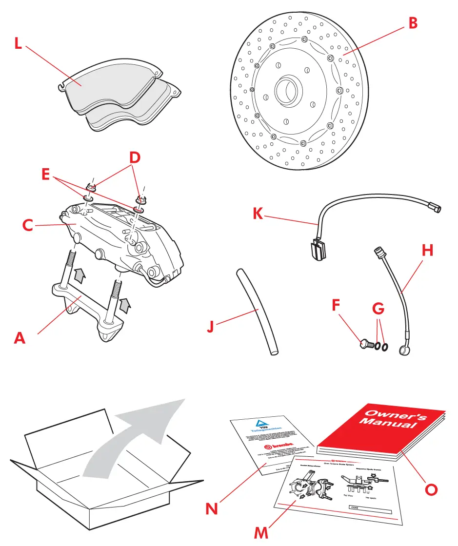
GT KIT components
The GT kit components list is given below: each pair of boxes contains all the components necessary for one vehicle axle. Some parts of the kit are directional and must be assembled on the correct side of the vehicle. These parts are packed separately in the 2 boxes with identification of the reference side:
| A. | Bracket (where scheduled with axially mounted caliper) | 1+1 |
| B. | Disc | 1+1 |
| C. | Caliper compete with pads (for some models the pads are separate) | 1+1 |
| D. E. | Screws/nuts and washers | 4+4 |
| F. | Pipe union or banjo fitting | 1+1 |
| G. | Copper washers (1 for adapter pipe union, 2 for banjo fitting) | 1+1 / 2+2 |
| H. | Supply pipe | 1+1 |
| J. | Bleed pipe | 1+1 |
| K. | Weak indicator (where scheduled) | 1+1 |
| L. | Set of pads (excluding kits with calipers already provided with pre-fitted pads) | 1+1 |
| M. | Bracket fixing diagram | 1 |
| N. | Teilegutachten approval certificate, where scheduled | 1 |
| O. | User manual | 1 |
Equipment required
To assemble and disassemble the braking system, the following equipment is required:
- Box wrenches
- Torque wrench
- Pliers
- Screwdrivers
- Spacer
- Retractor
- Container
- 01 dial test indicator with magnetic base
- Jack and supports
- Clean cloth
- Brake fluid
- Bleed pump
- Vehicle manufacturer’s manual
- Solvent for cleaning
- Rubber hammer
Choosing the wheels
Brembo recommends:
- The rolling diameter of the wheel should correspond to the value defined by the vehicle manufacturer,
- If large tyres are used, ensure that there are no impediments to rotation in all vehicle operating conditions
Failure to observe these preliminary recommendations can result in incorrect reading of the vehicle speed or, at worst, serious damage to the structure of the tyres and therefore risks in terms of vehicle stability. Due to the greater overall dimensions of disc and caliper, it may be necessary to use different rims or spacers.
Disc rotation direction
It is a common error to assume that the rotation direction of the disc is determined by the slots or the holes. For a ventilated disc, the rotation direction is determined by the geometry of the fins. Three types of ventilation are used:
- Straight fin
- Pillars
- Curved fins
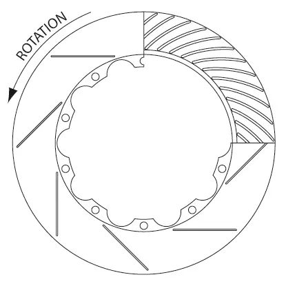
All the Brembo slotted discs are directional, regardless of the geometry of the ventilation fins. The discs should be installed so that the slot edges nearest the outer edge of the disc come into contact first with the pad.
Positioning the caliper
The Brembo calipers are directional and suitable precautions are taken during manufacture to avoid abnormal wear on the pads. The caliper bears a small arrow indicating the disc rotation direction. Once installed in the vehicle, the bleed screw will be in the upper part of the caliper.
Floating disc
To join composite discs, Brembo uses floating drive elements. The disc assembly system allows for a certain amount of play in both the radial and axial directions. Brembo has developed special springs which, when used in the drive elements, are designed to slightly pre-charge the assembled part. This prevents excessive noise being produced by the braking system. These springs can be found on all the drive elements or in alternating sequence according to specific application needs. Bushes without springs can move slightly in an axial direction; this is a fundamental requirement. The drive element tightening screws are tightened to an appropriate torque during the assembly process and must not be tightened any further or loosened for any reason.
Pads
The Brembo braking system pads are high quality and guarantee constant performance at the various temperatures. The pads are effective both at low temperatures and at the high temperatures reached during road racing. For the use of alternative friction materials, you are advised to contact Brembo for suggestions. The GT system pads can be without wear indicator. Periodic inspection of the pads is recommended to prevent damage to the disc due to excess wear on the pads.
The pads are worn out when the friction material reaches a thickness of 2 mm.
The pads are worn out when the friction material reaches a thickness of 2 mm.
Installation procedure
Lifting the vehicle
1. Slightly loosen the vehicle screws or nuts before lifting the vehicle.
2. Lift the vehicle carefully using the lifting points indicated in the vehicle manufacturer’s manual.
3. Prop the vehicle by means of supports, following the vehicle manufacturer’s recommendations.
4. Remove the wheel
2. Lift the vehicle carefully using the lifting points indicated in the vehicle manufacturer’s manual.
3. Prop the vehicle by means of supports, following the vehicle manufacturer’s recommendations.
4. Remove the wheel
DANGER! Check that the vehicle is raised in a safe stable manner; if not, it could fall from the supports causing possible injury and damage.
DANGER! You are advised not to rely on the hydraulic jack to support the vehicle during the assembly and disassembly operations. Failure to observe the vehicle manufacturer’s directions for lifting and supporting can lead to serious accidents, death and/or material damage.
DANGER! You are advised not to rely on the hydraulic jack to support the vehicle during the assembly and disassembly operations. Failure to observe the vehicle manufacturer’s directions for lifting and supporting can lead to serious accidents, death and/or material damage.
Bypassing the wear indicator
CAUTION! This procedure applies only to vehicles equipped with electric wear indicator. If your vehicle does not have an electric wear indicator, go on to the point “Removing the original components”.
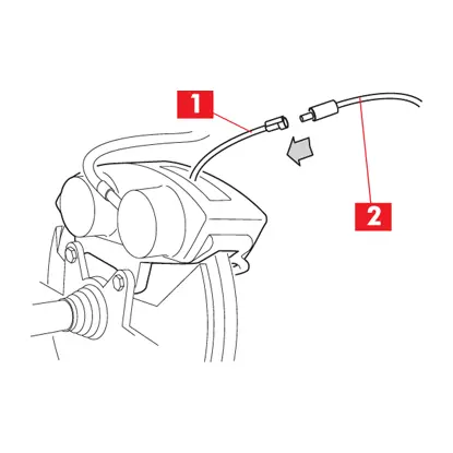
1. Disconnect the wear indicator cable (point 1) from the connector on the vehicle (point 2)
2. If the GT kit does not contain the wear indicator:
2. If the GT kit does not contain the wear indicator:
- Insert the keys in the ignition switch and turn them to the ignition ON position without starting the engine.
- If the wear indicator light remains off, re-set the key to the OFF position and fix the vehicle connector so that it does not get in the way and is not pulled or twisted by the movement of the steering and suspension.
- You are advised to use plastic clips. Go on to the point “Removing the original components”.
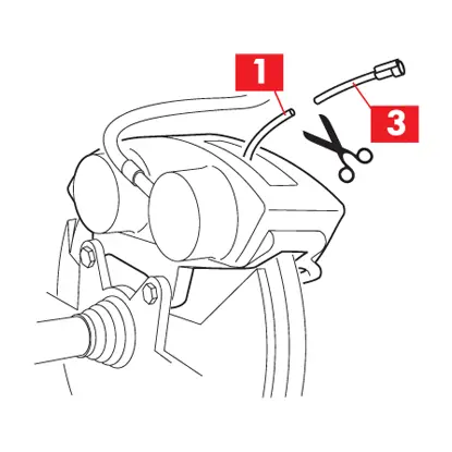
3. Cut the cable of the wear indicator (point 1) to 3-4 cm from the connection (point 3). Connect the two ends of the cable and insulate carefully. Reconnect the cable to the connector on the vehicle.
4. If the GT contains the wear indicator: repeat point 2:
- Connect the ends of the cable to the ends of the wear indicator supplied and insulate carefully.
- Reconnect the cable to the connector on the vehicle.
In all cases: - Turn the key in the ignition switch to the ON position without starting the engine.
- Check that the wear indicator light remains off. If it is on, re-check the electrical connections from step 2 and if necessary contact the Brembo customer service.
- Fix the vehicle connector so that it does not get in the way and is not pulled or twisted by the movement of the steering or suspension. You are advised to use plastic clips.
Removing the original components
CAUTIONS! During all the phases described below, make sure that the brake fluid does not come into contact with the parts of the vehicle that could be damaged, in particular the painted parts. Promptly absorb with paper and clean with water in the event of accidental splashes or leaks of brake fluid.
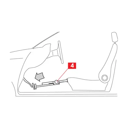
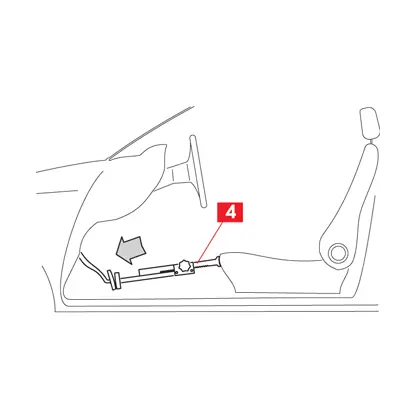
1. If the pump is not equipped with a non-emptying valve, press the brake pedal slightly to avoid leakage of the fluid. This will position the pump piston beyond the hole that connects the reservoir to the braking system.
To do this, enlist the help of another person or position a spacer (point 4) between the seat and the pedal so that the pedal is pressed down 3-5 cm. Do not press further.
To do this, enlist the help of another person or position a spacer (point 4) between the seat and the pedal so that the pedal is pressed down 3-5 cm. Do not press further.
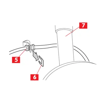
2. Disconnect the brake supply pipe from the connection to the chassis (point 5). Be careful not to damage the edges of the hexagon nut on the rigid pipe. You are advised to use a box wrench to tighten or loosen the fittings. Keep a rag and a container within easy reach to collect any brake fluid that may leak out. If provided, remove the safety clip (point 6) from the supply pipe (point 7).
CAUTION! For supply of the calipers, on some vehicles hoses (from the chassis to the suspension) and rigid pipes (from the suspension to the caliper) are used. In this case, remove the hoses and rigid pipes.
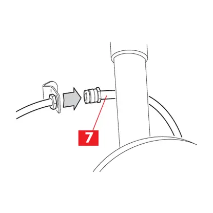
3. Disconnect the supply pipe (point 7) from the bracket on the chassis and from any other supper. The supply pipe must remain connected to the caliper. Use suitable plugs to seal the supply pipe (point 7) as soon as it is removed, thus preventing the entry of dust and dirt.
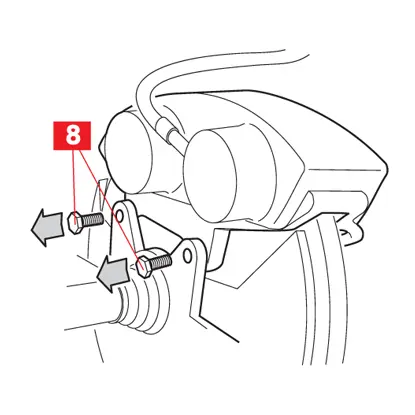
4. Remove the fastening screws (point 8) that fix the caliper on the spindle. Remove the caliper.
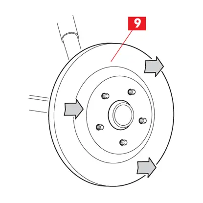
5. Identify and unscrew all the brake disc fastening nuts and screws. Remove the disc (point 9) from the seat. If provided, use the threaded hole on the disc bell as an aid if necessary. Insert a suitable screw and tighten it until the pressure exerted on the surface on the hub permits removal of the disc. If the threaded hole is not provided, use a rubber hammer, gently striking the rear part of the disc at various points until the disc moves and can then be removed.
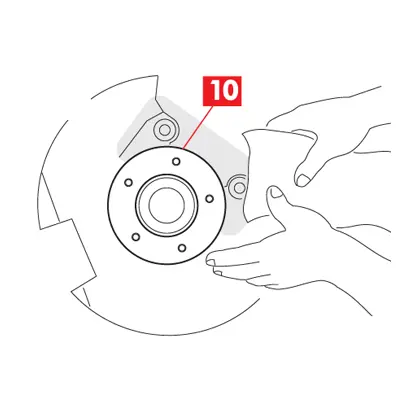
6. Thoroughly clean the surface of the caliper (point 10) using suitable materials and products (e.g. a damp cloth). Rust should be cleaned with wire wool or a metal brush.
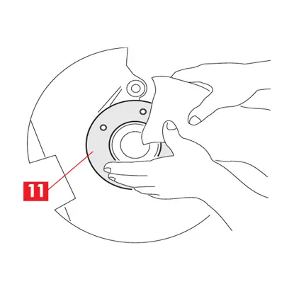
7. Thoroughly clean the surface of the disc (point 11) resting on the hub using suitable materials and products (e.g. a damp cloth). Rest should be cleaned with wire wool or a metal brush.
Installing the GT components
CAUTION! In many cases the new GT disc is larger than the original disc.
1. Temporarily position the new GT disc in its seat, ensuring a minimum gap of 3mm between the disc and dust plate.
2. If the gap between disc and dust plate is less than 3mm, remove the dust plate. Consult the vehicle manufacturer’s manual for removal of the plate.
3. If the GT kit does not contain the bracket, go on to the point 8.
WARNING! For correct assembly of the bracket, refer to the enclosed diagram M.
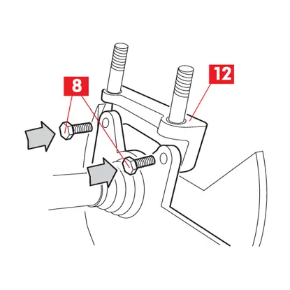
4. Fix the bracket (point 12) to the spindle using the new screws (point 8), if provided in the GT kit; alternatively use the original screws.
WARNING! Ensure that the surfaces of the bracket and spindle are fully in contact.
WARNING! Ensure that the surfaces of the bracket and spindle are fully in contact.
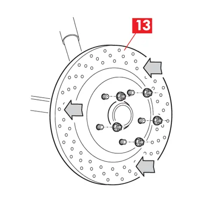
5. Position the disc (point 13) on the hub. If the original disc has holes for the spindle fastening screws, these will be provided also on the GT disc. To measure the oscillation, temporarily fir all the wheel fastening nuts or screws. Use different washers for each screw or stud bolt in order not to damage the bell and to ensure that the screws or nuts do not reach the end of the thread before fixing the disc. Tighten to a torque of 14 Nm.
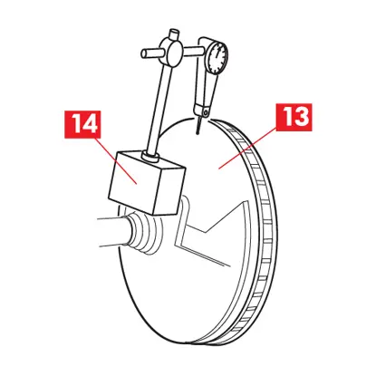
6. Position the magnetic base (point 14) of the dial test indicator on the surface of the caliper, or on an appropriately positioned metal support integral with the vehicle, ensuring that the base does not move during the measurement.
7. • Rest the tip on the dial test indicator on the internal braking surface of the disc (point 13) at approximately 3-5mm from the external diameter. Ensure that the tip does not come into contact with holes or slots during rotation of the disc. Rotate the disc one complete turn. The total oscillation must not exceed 0.07mm.
If oscillation exceeds this value, it can be reduced by removing the disc and rotating it 1/3, 1/4 or 1/5 of a turn, according to the number of fastening holes. Refit the disc and repeat the measurement. If your vehicle is provided with screws for fastening the disc to the hub, the above operation may not be possible. In this case, try discs taken from another kit for the same vehicle, if available. If the oscillation values continues to exceed the set limit, the hub or the spindle or the bearing are probably outside the specified limits. Consult the vehicle manufacturer’s manual to solve the problem.
WARNING! Do not use sealants or thread locking compounds on the screws or nuts fastening the caliper to the bracket.
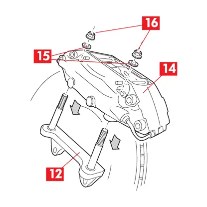
8. • Position the caliper (point 14) on the disc. If the bracket (point 12) is provided with stud bolts, ensure that the caliper is positioned as in the figure. Position a washer (point 15) (if scheduled) and a nut (point 16) on each stud bolt. The nuts are self-locking, the threaded hole is oval and it is not necessary to use threaded locking compound. Tighten each nut to a torque of 115 Nm.
If the bracket is without stud bolts, use the screws and any washers (if provided) to fix the caliper to the bracket. Tighten the screws to the torque prescribed in the table:
If the bracket is without stud bolts, use the screws and any washers (if provided) to fix the caliper to the bracket. Tighten the screws to the torque prescribed in the table:
| Screw type | Tightening torque |
| M12x1.5 | 115 Nm |
| M14x1.5 | 120 Nm |
WARNING! Do not use sealants or thread locking compounds on any of the pipe fittings.
9. Remove the threaded plastic cap from the supply hole on the caliper side.
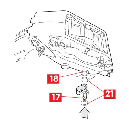
10. For the GT kit with adapter (point 17), insert a copper washer (point 21) on the short part and screw it into the caliper supply hole (point 18). Tighten to a torque of 20 Nm.
10. For the GT kit with adapter (point 17), insert a copper washer (point 21) on the short part and screw it into the caliper supply hole (point 18). Tighten to a torque of 20 Nm.
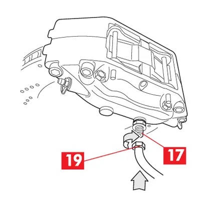
11. Screw the end of the supply pipe (point 19) to the adapter (point 17) without tightening, so that the fitting can rotate during the next stages of assembly, then go on to point 13.
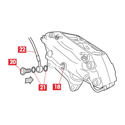
12. For kits supplied with banjo fitting, insert a capper washer (point 21) on the screw (point 20), insert the banjo fitting and then another copper washer (point 21). Screw everything into the caliper supply hole (point 18) without tightening, so that the fitting (point 22) can rotate during the next stages of assembly.
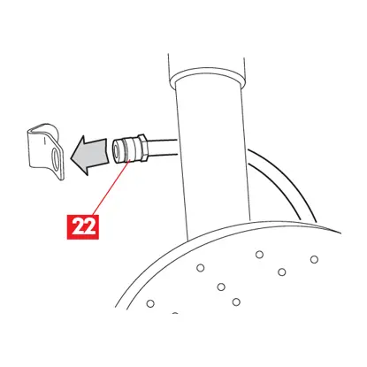
13. Secure the supply pipe to any supports. Insert the fitting (point 22) of the supply pipe in the bracket on the chassis, ensuring that it does not become twisted.
WARNING! In some cases, appropriately shaped adapters are supplied together with the pipes for the seat in the bracket on the chassis; if provided, they must be used. Refer to the specific assembly instructions provided with the kit. You are not allowed to modify (by machining) the seat in the bracket on the chassis.
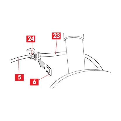
14. Reconnect the supply pipe (point 23) to the fluid supply system (point5) on the chassis. Fit any fastening clips (point 6). Tighten the fitting (point 24) to the torque prescribed by the vehicle manufacturer.
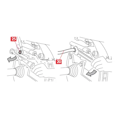
15. Tighten the end of the pipe to the adapter or the banjo fitting (point 20) to the caliper to a torque of 20 Nm. Ensure that the supply pipe does not become twisted.
DANGER! Temporarily fit the wheel and check that the supply pipe is positioned correctly. Check that the supply pipe is not pulled or twisted and comes into contact with the suspension, the chassis, the transmission and the rim during complete movement of the steering and suspension. Incorrect positioning of the supply pipe can cause leakage of the brake fluid and malfunctioning of the braking system with consequent danger of death, serious injury or damage to yourself and others.
16. Modify the path of the supply pipe if necessary.
17. Repeat these operations for the other side of the vehicle.
Bleeding
Perform bleeding according to the indications provided in the vehicle manufacturer’s manual; alternatively Brembo suggests the following.
DANGER! Air trapped in the hydraulic circuit seriously affects braking. Bleeding must be performed carefully and thoroughly. Use brake fluid of the type recommended by the vehicle manufacturer to avoid possible incompatibility between fluids. Take fluid only from sealed containers. There may be 1 or 2 bleed screws for each caliper. Bleeding must be repeated on all the screws of the system.
WARNING! During all the phases described below, ensure that the brake fluid does not come into contact with parts of the vehicle that could be damaged, in particular the painted parts. Promptly absorb any splashes or accidental leaks of brake fluid with paper and clean with water.
CAUTION! The braking systems of the most recent vehicles may be equipped with complex delicate safety systems (ABS, EBD,…). In these cases, bleeding of the braking system may have to be performed using the equipment specified by the vehicle manufacturer and following a different procedure from the one described below. Refer to the vehicle manufacturer’s manual and proceed according to the instructions provided.
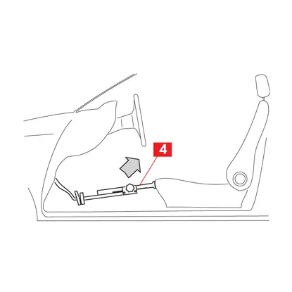
1. Remove the spacer (point 4) previously positioned inside the driver’s compartment, thus freeing the brake pedal and allowing the circuit to re-open.
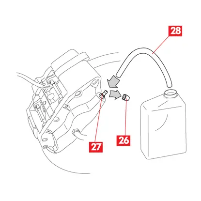
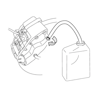
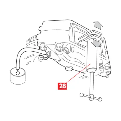
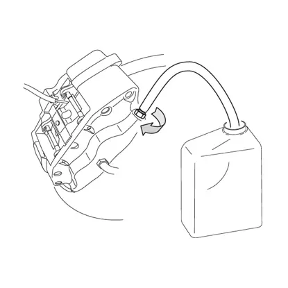
2. Remove the protective cap (point 26) and connect the transparent pipe (point 28) to the bleed screw (point 27) on the caliper; place a container at the end of the pipe to collect the fluid coming out.
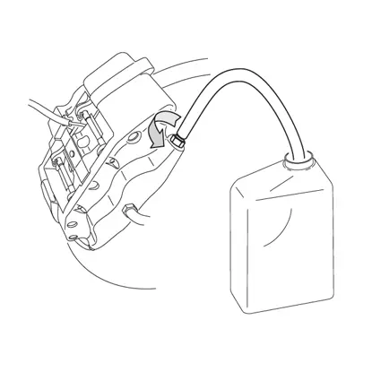
3. Open the bleed screw. Repeatedly operate the brake pedal in the vehicle until begins to come out of the bleed screw.
4. Keeping the pedal pressed, close the bleed screw. Release the pedal, wait a few seconds and then repeat the operations until brake fluid comes out without air bubbles and usual resistance and stroke of the brake pedal are restore. Repeat the bleeding procedure for any other bleed screws.
5. Keep the brake pedal pressed by positioning a spacer (point 4) between the seat and the pedal or enlist the help of another person.
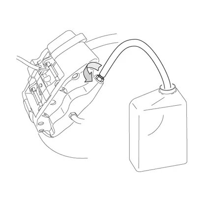
6. Loosen the bleed screw (point 27) 1/2 to 3/4 of a turn.
7. Use a suitable tool (e.g. a retractor (point 29)) to push the pistons into the brake caliper. This will help to expel the fluid and air present in the circuit. Close the bleed screw. Release the pistons and remove the spacer previously positioned inside the driver’s compartment.
8. Remove the transparent pipe and refit the protective cap on the bleed screw. Tighten the bleed screw to a torque of 14 Nm. Close the brake fluid reservoir plug. With the vehicle at a standstill, repeatedly operate the brake pedal until the usual pedal resistance is re-established. With the engine on, apply a strong pressure to the brake pedal in the vehicle and check that there are no leaks of fluid from the caliper or abnormal pressure drops in the circuit and that the rear brake lights come on. Refit the wheel.
DANGER! If the caliper leaks fluid, repeat all the operations described in this document to ascertain the cause and correct the problem.
Bedding in pads and discs
CAUTION! Carefully follow the procedure described below. Do not brake sharply.
DANGER! When the new pads have just been fitted, remember that braking performance is reduced, therefore you should:
- Slow down;
- Avoid sharp prolonged braking.
Drive carefully and perform at least 30 braking operations with medium/low deceleration lasting approximately 3 seconds, travelling at least 1 km between one breaking operation and another. Check the braking becomes smooth and without vibration. Drive the vehicle a few km without braking in order to cool the braking system. Re-check the braking; if it is smooth and without vibration, the braking system is ready for normal use. If the vehicle is stopped immediately after completion of the braking sequence, the heat from the discs could cause the brake fluid temperature to increase to above boiling point. In this case, bubbles are created in the brake fluid which, when the vehicle starts moving again, affect the braking capacity of the system resulting in danger of death, injury and damage.
Maintenance
Unless explicitly indicated, the system does not require any particular maintenance. Wear on the disc should be monitored, checking that the thickness does not drop below the minimum specified.
General and safety information
This product has been designed to comply with all applicable safety standards. Products are not intended to be used differently from the specific use for which they have been designed and manufactured. Use for any other purpose, or any modification to, or tampering with, the Product can affect the performance of the Product and may render the Product unsafe. Such modification or improper use will void the Limited Warranty, and may subject the individual so using the Product to liability for bodily injury or property damage to others.
As used in these instructions, “DANGER!” means procedures which, if not observed, have a high degree of probability that they will cause serious injury or even death. “WARNING!” means procedures which, if not observed, could possibly cause injury. “CAUTION!” means procedures which, if not observed, could result in damage to the vehicle. .
DANGER!
- This Product is vital to the safe operation of the vehicle on which it is installed, and it is intended to be installed only by a skilled, qualified individual who has been trained and/or is experienced in the installation and use for which the Product is intended. The installer must be equipped with the proper tools of his trade, and with the knowledge and experience to deal with vehicle repairs. Improper or incorrect installation, whether caused by a failure to faithfully and completely follow these Instructions or otherwise, will void the Limited Warranty and could subject the installer to liability in the event of personal injury or property damage.
Brembo shall not be liable for any damage or injury caused to or by any person operating a vehicle on which a replacement product has been improperly installed.
Avoid contact of grease and other lubricants with the braking surfaces of the disc and pads as this could affect the efficiency of the braking system and cause serious physical damage. Install the GT kit braking system on both sides. - Before commencing the replacement procedure, ensure that the material used for the replacement is suitable for the make and model of vehicle.
- This Brembo product has been designed to comply with all applicable safety standards. Products are not intended to be used differently from the specific use for which they have been designed and manufactured.
- Use for any other purpose, or any modification to, or tampering with, the Product can affect the performance of the Product and may render the Product unsafe.
- The used product replaced by this Product must not be installed on any other product. Property damage and personal injury, including death, could result.
- Always check that the brake fluid level in the reservoir is between the minimum and maximum levels indicated on the reservoir. An incorrect level can cause brake fluid leaks or reduced brake system efficiency. Too much or too little brake fluid in the reservoir could cause the brakes not to perform properly, and personal injury, including death, could result.
- Do not attempt to loosen or tighten the screws that hold the half-calipers together or secure shims or tie-rods to the caliper body, unless specifically required by this manual, and if so, only for the operations indicated.
- Do not remove the stud bolts.
WARNING!
- In the course of replacing the product, and related items such as brake fluid, brake pads, brake shoes, and the like, the installer will be exposed to fluids and parts that may be deemed to be “hazardous waste” under applicable laws, rules and regulations. All such wastes must be handles, recycled and(or disposed of in accordance with all applicable laws, rules and regulations. The failure to do so can subject the generator of the hazardous waste to penalties under environmental laws, and could result in bodily injury or property damage to the generator or others.
- To avoid creating a defective installation, avoid sharply striking and /or damaging the Product, its parts and its components, as this can impair their efficiency and may cause them to malfunction. If necessary, replace any damaged part or component.
- The GT kits are supplied in two packages to differentiate the right-hand side elements from the left-hand side elements. Ensure that the individual components are fitted correctly and do not mix the components of the two different packages.
- To avoid injury:
- Use suitable equipment to prevent the inhalation of dust raised during cleaning of the parts.
- Always wear gloves during disassembly and assembly of components with sharp edges.
- Do not allow skin surfaces to make direct contact between the pad and shoe linings since this could cause abrasions.
- Avoid direct contact with the brake fluid as it can cause irritation to the skin and eyes. In the event of contact, clean thoroughly in accordance with the vehicle or brake fluid manufacturer’s instructions.
- Ensure correct connection of any electrical contacts, checking that the warning lights come on. If they do not, non-operation of the warning lights can cause a reduction in efficiency of the braking system, or brake signaling failure
CAUTIONS!
- Do not remove the braking ring from the bell. For composite discs, the bells are also subject to wear, therefore replacement of a worn floating disc involves complete replacement of the assembly and not only the ring.
- Brembo advises you to measure the oscillation of the disc during installation to ensure that the hub, the spindle and the bearing are in perfect order and aligned. If the procedure is not carried out and a vibration problem occurs, Brembo accepts no liability for recognition of the warranty.
- The fixes calipers like those contained in the kit transmit more vibration of all types to the brake pedal (except for system with electronic braking system) and/or to the steering wheel.
- Even if the bearings, all parts of the suspension, bushes, heads, axle shafts, rims, tyres etc. … are not excessively worn after limited use, they must be checked in accordance with the vehicle manufacturer’s manual and, if necessary, replaced before installing a GT kit.
Warranty limitations
This warranty covers all the conformity defects occurring within two years from delivery of the good. The consumer is required to report to the seller the conformity defect within two months from the date of discovery of the said defect, without prejudice to the fact that the limitations period for taking action aimed at seeking redress for the defect is twenty-six months from delivery of the good. In the event of a conformity defect, the user has the right to repair or replacement of the good, or to an appropriate price reduction or termination of the contract, as established by art. 130 of the Consumer Code, where applicable.This warranty constitutes the only warranty provided in relation to this product and replaces any other warranties, both verbal and written.
Θέλετε να ρωτήσετε κάτι άλλο;
Επικοινωνήστε με το τμήμα τεχνικής υποστήριξης της Brembo. Οι τεχνικοί μας θα επικοινωνήσουν μαζί σας το συντομότερο δυνατό!